
Page 106 - The Jet Engine
P. 106
Fuel system
power lever. A fuel shut-off valve (cock) control lever
is also used to stop the engine, although in some
instances these two manual controls are combined
for single-lever operation.
2. It is also necessary to have automatic safety
controls that prevent the engine gas temperature,
compressor delivery pressure, and the rotating
assembly speed, from exceeding their maximum
limitations.
3. With the turbo-propeller engine, changes in
propeller speed and pitch have to be taken into
account due to their effect on the power output of the
engine. Thus, it is usual to interconnect the throttle
lever and propeller controller unit, for by so doing the
correct relationship between fuel flow and airflow is
maintained at all engine speeds and the pilot is given
single-lever control of the engine. Although the
maximum speed of the engine is normally
determined by the propeller speed controller, over-
speeding is ultimately prevented by a governor in the
fuel system.
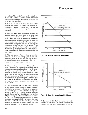
4. The fuel system often provides for ancillary Fig. 10-1 Airflow changing with altitude.
functions, such as oil cooling (Part 8) and the
hydraulic control of various engine control systems;
for example, compressor airflow control (Part 3).
MANUAL AND AUTOMATIC CONTROL
5. The control of power or thrust of the gas turbine
engine is effected by regulating the quantity of fuel
injected into the combustion system. When a higher
thrust is required, the throttle is opened and the
pressure to the fuel spray nozzles increases due to
the greater fuel flow. This has the effect of increasing
the gas temperature, which in turn increases the
acceleration of the gases through the turbine to give
a higher engine speed and a correspondingly greater
airflow, consequently producing an increase in
engine thrust.
6. This relationship between the airflow induced
through the engine and the fuel supplied is, however,
complicated by changes in altitude, air temperature
and aircraft speed. These variables change the
density of the air at the engine intake and conse-
quently the mass of air induced through the engine.
A typical change of airflow with altitude is shown in Fig. 10-2 Fuel flow changing with altitude.
fig. 10-1. To meet this change in airflow a similar
change in fuel flow (fig. 10-2) must occur, otherwise
the ratio of airflow to fuel flow will change and will 7. Described in this Part are five representative
increase or decrease the engine speed from that systems of automatic fuel control; these are the
originally selected by the throttle lever position. pressure control and flow control systems, which are
96