
Page 101 - The Jet Engine
P. 101
Internal air system
Hydraulic seals
19. This method of sealing is often used between
two rotating members to sea a bearing chamber.
Unlike the labyrinth or ring seal, it does not allow a
controlled flow of air to traverse across the seal,
20. Hydraulic seals (fig. 9-7) are formed by a seal
fin immersed in an annulus of oil which has been
created by centrifugal forces. Any difference in air
pressure inside and outside of the bearing chamber
is compensated by a difference in oil level either side
of the fin.
Carbon seals
21. Carbon seals (fig. 9-7) consist of a static ring of
carbon which constantly rubs against a collar on a
rotating shaft. Several springs are used to maintain
contact between the carbon and the collar. This type
of seal relies upon a high degree of contact and does
not allow oil or air leakage across it. The heat caused
by friction is dissipated by the oil system.
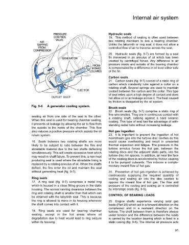
Fig. 9-6 A generator cooling system. Brush seals
22. Brush seals (fig. 9-7) comprise a static ring of
fine wire bristles. They are in continuous contact with
sealing air from one side of the seal to the other. a rotating shaft, rubbing against a hard ceramic
When this seal is used for bearing chamber sealing, coating. This type of seal has the advantage of with-
it prevents oil leakage by allowing the air to flow from standing radial rubs without increasing leakage.
the outside to the inside of the chamber. This flow
also induces a positive pressure which assists the oil Hot gas ingestion
return system. 23. It is important to prevent the ingestion of hot
mainstream gas into the turbine disc cavities as this
16. Seals between two rotating shafts are more would cause overheating and result in unwanted
likely to be subject to rubs between the fins and thermal expansion and fatigue. The pressure in the
abradable material due to the two shafts deflecting turbine annulus forces the hot gas, between the
simultaneously. This will create excessive heat which rotating discs and the adjacent static parts, into the
may result in shaft failure. To prevent this, a non-heat turbine disc rim spaces. In addition, air near the face
producing seal is used where the abradable lining is of the rotating discs is accelerated by friction causing
it to be pumped outwards. This induces a comple-
replaced by a rotating annulus of oil. When the shafts mentary inward flow of hot gas.
deflect, the fins enter the oil and maintain the seal
without generating heat (fig. 9-7). 24. Prevention of hot gas ingestion is achieved by
continuously supplying the required quantity of
Ring seals cooling and sealing air into the disc cavities to
17. A ring seal (fig. 9-7) comprises a metal ring oppose the inward flow of hot gas. The flow and
which is housed in a close fitting groove in the static pressure of the cooling and sealing air is controlled
housing. The normal running clearance between the by interstage seals (fig. 9-5),
ring and rotating shaft is smaller than that which can CONTROL OF BEARING LOADS
be obtained with the labyrinth seal. This is because
the ring is allowed to move in its housing whenever 25. Engine shafts experience varying axial gas
the shaft comes into contact with it. loads (Part 20) which act in a forward direction on the
compressor and in a rearward direction on the
18. Ring seals are used for bearing chamber turbine. The shaft between them is therefore always
sealing, except in the hot areas where oil under tension and the difference between the loads
degradation due to heat would lead to ring seizure is carried by the location bearing which is fixed in a
within its housing. static casing (fig. 9-8). The internal air pressure acts
91