
Page 99 - The Jet Engine
P. 99
Internal air system
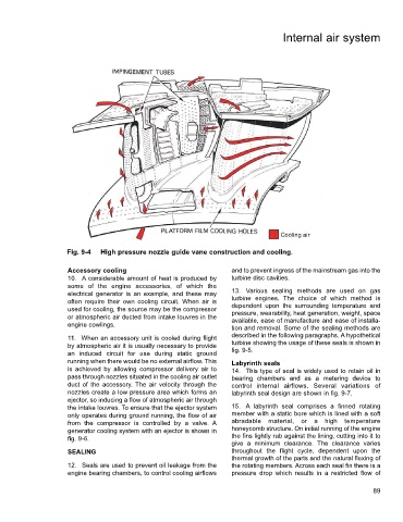
Fig. 9-4 High pressure nozzle guide vane construction and cooling.
Accessory cooling and to prevent ingress of the mainstream gas into the
10. A considerable amount of heat is produced by turbine disc cavities.
some of the engine accessories, of which the
electrical generator is an example, and these may 13. Various sealing methods are used on gas
often require their own cooling circuit. When air is turbine engines. The choice of which method is
dependent upon the surrounding temperature and
used for cooling, the source may be the compressor pressure, wearability, heat generation, weight, space
or atmospheric air ducted from intake louvres in the available, ease of manufacture and ease of installa-
engine cowlings.
tion and removal. Some of the sealing methods are
11. When an accessory unit is cooled during flight described in the following paragraphs. A hypothetical
by atmospheric air it is usually necessary to provide turbine showing the usage of these seals is shown in
an induced circuit for use during static ground fig. 9-5.
running when there would be no external airflow. This Labyrinth seals
is achieved by allowing compressor delivery air to 14. This type of seal is widely used to retain oil in
pass through nozzles situated in the cooling air outlet bearing chambers and as a metering device to
duct of the accessory. The air velocity through the control internal airflows. Several variations of
nozzles create a low pressure area which forms an labyrinth seal design are shown in fig. 9-7.
ejector, so inducing a flow of atmospheric air through
the intake louvres. To ensure that the ejector system 15. A labyrinth seal comprises a finned rotating
only operates during ground running, the flow of air member with a static bore which is lined with a soft
from the compressor is controlled by a valve. A abradable material, or a high temperature
generator cooling system with an ejector is shown in honeycomb structure. On initial running of the engine
fig. 9-6. the fins lightly rub against the lining, cutting into it to
give a minimum clearance. The clearance varies
SEALING throughout the flight cycle, dependent upon the
thermal growth of the parts and the natural flexing of
12. Seals are used to prevent oil leakage from the the rotating members. Across each seal fin there is a
engine bearing chambers, to control cooling airflows pressure drop which results in a restricted flow of
89