
Page 98 - The Jet Engine
P. 98
Internal air system
6. An air cooled high pressure nozzle guide vane substantial whirl velocity to assist efficient entry of
and turbine blade arrangement illustrating the the air into the rotating cooling passages.
cooling airflow is shown in fig. 9-2. Turbine vane and 8. Cooling air for the turbine discs enters the
turbine blade life depends not only on their form but annular spaces between the discs and flows
also on the method of cooling, therefore the flow outwards over the disc faces. Flow is controlled by
design of the internal passages is important. There interstage seals and, on completion of the cooling
have been numerous methods of turbine vane and function, the air is expelled into the main gas stream
turbine blade cooling which have been used (fig. 9-5); see para. 23., Hot gas ingestion.
throughout the history of gas turbines. Generally, Bearing chamber cooling
single pass internal (convection) cooling was of great 9. Air cooling of the engine bearing chambers is not
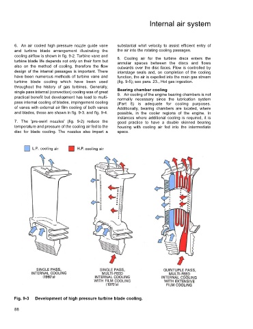
practical benefit but development has lead to multi- normally necessary since the lubrication system
pass internal cooling of blades, impingement cooling (Part 8) is adequate for cooling purposes.
of vanes with external air film cooling of both vanes Additionally, bearing chambers are located, where
and blades, these are shown in fig. 9-3. and fig. 9-4. possible, in the cooler regions of the engine. In
instances where additional cooling is required, it is
7. The 'pre-swirl nozzles' (fig. 9-2) reduce the good practice to have a double skinned bearing
temperature and pressure of the cooling air fed to the housing with cooling air fed into the intermediate
disc for blade cooling. The nozzles also impart a space.
Fig. 9-3 Development of high pressure turbine blade cooling.
88