
Page 96 - The Jet Engine
P. 96
Internal air system
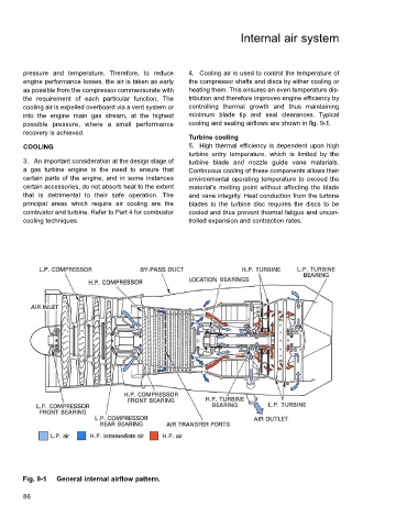
pressure and temperature. Therefore, to reduce 4. Cooling air is used to control the temperature of
engine performance losses, the air is taken as early the compressor shafts and discs by either cooling or
as possible from the compressor commensurate with heating them. This ensures an even temperature dis-
the requirement of each particular function. The tribution and therefore improves engine efficiency by
cooling air is expelled overboard via a vent system or controlling thermal growth and thus maintaining
into the engine main gas stream, at the highest minimum blade tip and seal clearances. Typical
possible pressure, where a small performance cooling and sealing airflows are shown in fig. 9-1.
recovery is achieved.
Turbine cooling
COOLING 5. High thermal efficiency is dependent upon high
turbine entry temperature, which is limited by the
3. An important consideration at the design stage of turbine blade and nozzle guide vane materials.
a gas turbine engine is the need to ensure that Continuous cooling of these components allows their
certain parts of the engine, and in some instances environmental operating temperature to exceed the
certain accessories, do not absorb heat to the extent material's melting point without affecting the blade
that is detrimental to their safe operation. The and vane integrity. Heat conduction from the turbine
principal areas which require air cooling are the blades to the turbine disc requires the discs to be
combustor and turbine. Refer to Part 4 for combustor cooled and thus prevent thermal fatigue and uncon-
cooling techniques. trolled expansion and contraction rates.
Fig. 9-1 General internal airflow pattern.
86