
Page 91 - The Jet Engine
P. 91
Lubrication
debris from each bearing chamber. They are
basically permanent magnets inserted in the oil flow
and are retained in self-sealing valve housings.
Safety features incorporated in the design ensure
correct retention within the housing. Upon
examination they can provide a warning of
impending failure without having to remove and
inspect the filters. They are designed to be removed
during maintenance inspection, for condition,
monitoring purposes (Part 24), without oil loss
occurring. Additionally they may be connected to a
cockpit warning system to give an in-flight indication.
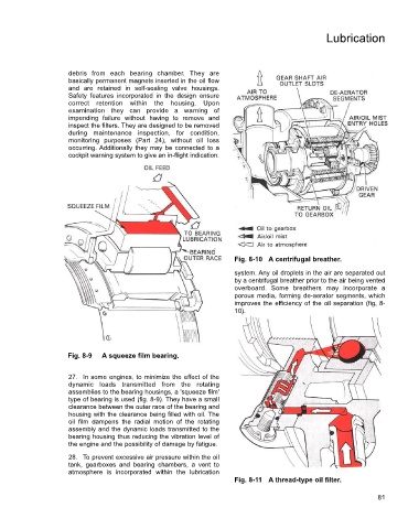
Fig. 8-10 A centrifugal breather.
system. Any oil droplets in the air are separated out
by a centrifugal breather prior to the air being vented
overboard. Some breathers may incorporate a
porous media, forming de-aerator segments, which
improves the efficiency of the oil separation (fig, 8-
10).
Fig. 8-9 A squeeze film bearing.
27. In some engines, to minimize the effect of the
dynamic loads transmitted from the rotating
assemblies to the bearing housings, a 'squeeze film'
type of bearing is used (fig. 8-9). They have a small
clearance between the outer race of the bearing and
housing with the clearance being filled with oil. The
oil film dampens the radial motion of the rotating
assembly and the dynamic loads transmitted to the
bearing housing thus reducing the vibration level of
the engine and the possibility of damage by fatigue.
28. To prevent excessive air pressure within the oil
tank, gearboxes and bearing chambers, a vent to
atmosphere is incorporated within the lubrication
Fig. 8-11 A thread-type oil filter.
81