
Page 119 - The Jet Engine
P. 119
Fuel system
main fuel pressure and it is not shut off by the known as a variable metering sleeve, has a
pressure drop control piston. It therefore gives a sat- triangular orifice, known as the variable metering
isfactory idling fuel flow at all altitudes. orifice (V.M.O.), and this sleeve is given axial
movement by a capsule assembly. The other valve,
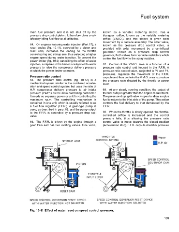
64. On engines featuring water injection (Part 17), a known as the pressure drop control valve, is
reset device (fig. 10-11), operated by a piston and provided with axial movement by a centrifugal
reset cam, increases the loading on the throttle governor, known as a pressure drop control
control spring and stirrup arm, thus selecting a higher governor, Both valves form variable restrictors which
engine speed during water injection. To prevent the control the fuel flow to the spray nozzles.
power limiter (fig, 10-9) cancelling the effect of water
injection, a capsule in the limiter is subjected to water 67. Control of the V.M.O. area is a function of a
pressure to raise the compressor delivery pressure pressure ratio control unit housed in the F.F.R. A
at which the power limiter operates. pressure ratio control valve, subjected to P4 and P1,
pressures, regulates the movement of the F.F.R.
Pressure ratio control capsule and thus controls the V.M.O. area to produce
65. The pressure ratio control (fig. 10-12) is a the pressure ratio dictated by the throttle or power
mechanical system similar to the combined acceler- lever.
ation and speed control system, but uses the ratio of
H.P. compressor delivery pressure to air intake 68. At any steady running condition, the output of
pressure (P4/P1) as the main controlling parameter. the fuel pump is greater than the engine requirement.
It needs no separate governor unit for controlling the The pressure drop spill valve is open to allow surplus
maximum r.p.m. The controlling mechanism is fuel to return to the inlet side of the pump. This action
contained in one unit, which is usually referred to as controls the fuel delivery to that demanded by the
a fuel flow regulator (F.F.R.). A gear-type pump is F.F.R.
used, as described in para. 88, and the pump output
to the F.F.R. is controlled by a pressure drop spill 69. When the throttle is slowly opened, the throttle-
valve. controlled orifice is increased and the control
pressure falls, thus allowing the pressure ratio
66. The F.F.R. is driven by the engine through a control valve to move towards the closed position
gear train and has two rotating valves. One valve, (acceleration stop). F.F.R. capsule chamber pressure
Fig. 10-11 Effect of water reset on speed control governor.
109