
Page 124 - The Jet Engine
P. 124
Fuel system
square inch. To drive this pump, as much as 60
horsepower may be required.
87. The fuel pump consists of a rotor assembly
fitted with several plungers, the ends of which project
from their bores and bear on to a non-rotating
camplate. Due to the inclination of the camplate,
movement of the rotor imparts a reciprocating motion
to the plungers, thus producing a pumping action.
The stroke of the plungers is determined by the angle
of inclination of the camplate. The degree of
inclination is varied by the movement of a servo
piston that is mechanically linked to the camplate
and is biased by springs to give the full stroke
position of the plungers. The piston is subjected to
servo pressure on the spring side and on the other
side to pump delivery pressure; thus variations in the
pressure difference across the servo piston cause it
to move with corresponding variations of the
camplate angle and, therefore, pump stroke.
Gear-type fuel pump
88. The gear-type fuel pump (fig. 10-12) is driven
from the engine and its output is directly proportional
to its speed. The fuel flow to the spray nozzles is
controlled by recirculating excess fuel delivery back
to inlet. A spill valve, sensitive to the pressure drop
across the controlling units in the system, opens and
closes as necessary to increase or decrease the
spill.
FUEL SPRAY NOZZLES
89. The final components of the fuel system are the
fuel spray nozzles, which have as their essential
function the task of atomizing or vaporizing the fuel to
ensure its rapid burning. The difficulties involved in Fig. 10-15 Various stages of fuel atomization.
this process can be readily appreciated when one
considers the velocity of the air stream from the high velocity air instead of high velocity fuel to cause
compressor and the short length of combustion atomization. This method allows atomization at low
system (Part 4) in which the burning must be fuel flow rates (provided sufficient air velocity exists)
completed.
thus providing an advantage over the pressure jet
atomizer by allowing fuel pumps of a lighter con-
90. An early method of atomizing the fuel is to pass
it through a swirl chamber where tangentially struction to be used.
disposed holes or slots imparted swirl to the fuel by 91. The atomizing spray nozzle, as distinct from the
converting its pressure energy to kinetic energy. In vaporizing burner (Part 4), has been developed in
this state, the fuel is passed through the discharge five fairly distinct types; the Simplex, the variable port
orifice which removes the swirl motion as the fuel is (Lubbock), the Duplex or Duple, the spill type and the
atomized to form a cone-shaped spray. This is called airspray nozzle.
'pressure jet atomization'. The rate of swirl and
pressure of the fuel at the fuel spray nozzle are 92. The Simplex spray nozzle shown in fig. 10-16
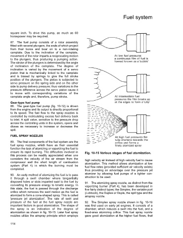
important factors in good atomization. The shape of was first used on early jet engines. It consists of a
the spray is an indication of the degree of chamber, which induces a swirl into the fuel, and a
atomization as shown in fig. 10-15. Later fuel spray fixed-area atomizing orifice. This fuel spray nozzle
nozzles utilize the airspray principle which employs gave good atomization at the higher fuel flows, that
114