
Page 170 - The Jet Engine
P. 170
Thrust reversal
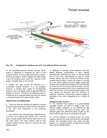
Fig. 15-1 Comparative landing runs with and without thrust reversal.
4. On propeller-powered aircraft, reverse thrust 8. Methods of reverse thrust selection and the
action is obtained by changing the pitch of the safety features incorporated in each system
propeller blades. This is usually achieved by a hydro- described are basically the same. A reverse thrust
mechanical system, which changes the blade angle lever in the crew compartment is used to select
to give the braking action under the response of the reverse thrust; the lever cannot be moved to the
power or throttle lever in the aircraft. reverse thrust position unless the engine is running
at a low power setting, and the engine cannot be
5. Ideally, the gas should be directed in a opened up to a high power setting if the reverser fails
completely forward direction. It is not possible, to move into the full reverse thrust position. Should
however, to achieve this, mainly for aerodynamic the operating pressure fall or fail, a mechanical lock
reasons, and a discharge angle of approximately 45 holds the reverser in the forward thrust position; this
degrees is chosen. Therefore, the effective power in lock cannot be removed until the pressure is
restored. Operation of the thrust reverser system is
reverse thrust is proportionately less than the power indicated in the crew compartment by a series of
in forward thrust for the same throttle angle.
lights.
PRINCIPLES OF OPERATION
Clamshell door system
6. There are several methods of obtaining reverse 9. The clamshell door system is a pneumatically
thrust on turbo-jet engines; three of these are shown operated system, as shown in detail in fig. 15-3.
in fig. 15-2 and explained in the following Normal engine operation is not affected by the
system, because the ducts through which the
paragraphs. exhaust gases are deflected remain closed by the
7. One method uses clamshell-type deflector doors doors until reverse thrust is selected by the pilot.
to reverse the exhaust gas stream and a second 10. On the selection of reverse thrust, the doors
uses a target system with external type doors to do rotate to uncover the ducts and close the normal gas
the same thing. The third method used on fan stream exit. Cascade vanes then direct the gas
engines utilizes blocker doors to reverse the cold stream in a forward direction so that the jet thrust
stream airflow. opposes the aircraft motion.
160