
Page 176 - The Jet Engine
P. 176
Thrust reversal
directs oil from the control system to the propeller pipe. The reverser casing is connected to the aircraft
mechanism to reduce the blade angle to zero, and structure or directly to the engine. The casing
then through to negative (reverse) pitch. During supports the two reverser doors, the operating
throttle lever movement, the fuel to the engine is mechanism and, in the case of the clamshell door
trimmed by the throttle valve, which is interconnect- system, the outlet ducts that contain the cascade
ed to the pitch control unit, so that engine power and vanes. The angle and area of the gas stream are
blade angle are co-ordinated to obtain the desired controlled by the number of vanes in each outlet
amount of reverse thrust. Reverse thrust action may duct.
also be used to manoeuvre a turbo-propeller aircraft
backwards after it has been brought to rest. 21. The clamshell and bucket target doors lie flush
with the casing during forward thrust operation and
19. Several safety factors are incorporated in the are hinged along the centre line of the jet pipe. They
propeller control system for use in the event of are, therefore, in line with the main gas load and this
propeller malfunction, and these devices are usually ensures that the minimum force is required to move
hydro-mechanical pitch locking devices or stops. the doors.
CONSTRUCTION AND MATERIALS 22. Both the clamshell door system and the bucket
target system are subjected to high temperatures
20. The clamshell and bucket target doors (fig. 15- and to high gas loads. The components of both
6) described in paras. 9 and 12 form part of the jet systems, especially the doors, are therefore
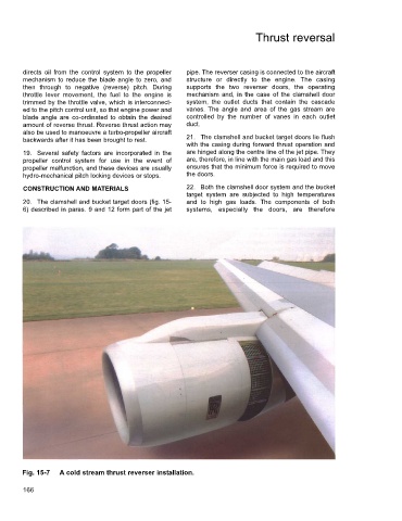
Fig. 15-7 A cold stream thrust reverser installation.
166