
Page 180 - The Jet Engine
P. 180
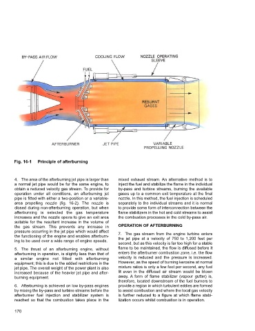
Fig. 16-1  Principle of afterburning


        4. The area of the afterburning jet pipe is larger than  mixed exhaust stream. An alternative method is to
        a normal jet pipe would be for the same engine, to  inject the fuel and stabilize the flame in the individual
        obtain a reduced velocity gas stream. To provide for  by-pass and turbine streams, burning the available
        operation under all conditions, an afterburning jet  gases up to a common exit temperature at the final
        pipe is fitted with either a two-position or a variable-  nozzle. In this method, the fuel injection is scheduled
        area propelling nozzle (fig. 16-2).  The nozzle is  separately to the individual streams and it is normal
        closed during non-afterburning operation, but when  to provide some form of interconnection between the
        afterburning is selected the gas temperature      flame stabilizers in the hot and cold streams to assist
        increases and the nozzle opens to give an exit area  the combustion processes in the cold by-pass air.
        suitable for the resultant increase in the volume of
        the gas stream.  This prevents any increase in    OPERATION OF AFTERBURNING
        pressure occurring in the jet pipe which would affect  7. The gas stream from the engine turbine enters
        the functioning of the engine and enables afterburn-  the jet pipe at a velocity of 750 to 1,200 feet per
        ing to be used over a wide range of engine speeds.
                                                          second, but as this velocity is far too high for a stable
        5. The thrust of an afterburning engine, without  flame to be maintained, the flow is diffused before it
        afterburning in operation, is slightly less than that of  enters the afterburner combustion zone, i.e. the flow
        a similar engine not fitted with afterburning     velocity is reduced and the pressure is increased.
        equipment; this is due to the added restrictions in the  However, as the speed of burning kerosine at normal
        jet pipe. The overall weight of the power plant is also  mixture ratios is only a few feet per second, any fuel
        increased because of the heavier jet pipe and after-  lit even in the diffused air stream would be blown
        burning equipment.                                away. A form of flame stabilizer (vapour gutter) is,
                                                          therefore, located downstream of the fuel burners to
        6. Afterburning is achieved on low by-pass engines  provide a region in which turbulent eddies are formed
        by mixing the by-pass and turbine streams before the  to assist combustion and where the local gas velocity
        afterburner fuel injection and stabilizer system is  is further reduced to a figure at which flame stabi-
        reached so that the combustion takes place in the  lization occurs whilst combustion is in operation.

        170