
Page 184 - The Jet Engine
P. 184
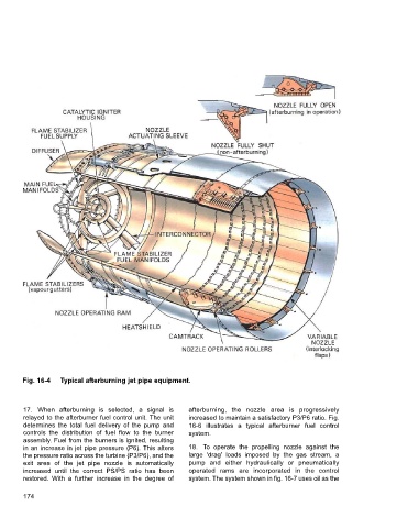
Fig. 16-4  Typical afterburning jet pipe equipment.


        17. When afterburning is selected, a signal is    afterburning, the nozzle area is progressively
        relayed to the afterburner fuel control unit. The unit  increased to maintain a satisfactory P3/P6 ratio. Fig.
        determines the total fuel delivery of the pump and  16-6 illustrates a typical afterburner fuel control
        controls the distribution of fuel flow to the burner  system.
        assembly. Fuel from the burners is ignited, resulting
        in an increase in jet pipe pressure (P6). This alters  18. To operate the propelling nozzle against the
        the pressure ratio across the turbine (P3/P6), and the  large 'drag' loads imposed by the gas stream, a
        exit area of the jet pipe nozzle is automatically  pump and either hydraulically or pneumatically
        increased until the correct PS/PS ratio has been  operated rams are incorporated in the control
        restored. With a further increase in the degree of  system. The system shown in fig. 16-7 uses oil as the

        174