
Page 22 - The Jet Engine
P. 22
Working cycle and airflow
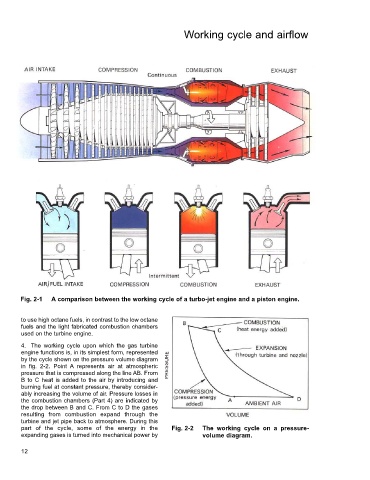
Fig. 2-1 A comparison between the working cycle of a turbo-jet engine and a piston engine.
to use high octane fuels, in contrast to the low octane
fuels and the light fabricated combustion chambers
used on the turbine engine.
4. The working cycle upon which the gas turbine
engine functions is, in its simplest form, represented
by the cycle shown on the pressure volume diagram
in fig. 2-2. Point A represents air at atmospheric
pressure that is compressed along the line AB. From
B to C heat is added to the air by introducing and
burning fuel at constant pressure, thereby consider-
ably increasing the volume of air. Pressure losses in
the combustion chambers (Part 4) are indicated by
the drop between B and C. From C to D the gases
resulting from combustion expand through the
turbine and jet pipe back to atmosphere. During this
part of the cycle, some of the energy in the Fig. 2-2 The working cycle on a pressure-
expanding gases is turned into mechanical power by volume diagram.
12