
Page 24 - The Jet Engine
P. 24
Working cycle and airflow
stages. This relationship applies for whatever means the air that provides the thrust on the aircraft. Local
are used to change the state of the air. For example, decelerations of airflow are also required, as for
whether energy is added by combustion or by instance, in the combustion chambers to provide a
compression, or is extracted by the turbine, the heat low velocity zone for the flame to burn.
change is directly proportional to the work added or
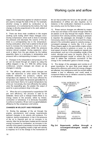
taken from the gas. 13. These various changes are effected by means
of the size and shape of the ducts through which the
8. There are three main conditions in the engine air passes on its way through the engine. Where a
working cycle during which these changes occur. conversion from velocity (kinetic) energy to pressure
During compression, when work is done to increase is required, the passages are divergent in shape.
the pressure and decrease the volume of the air, Conversely, where it is required to convert the energy
there is a corresponding rise in the temperature. stored in the combustion gases to velocity energy, a
During combustion, when fuel is added to the air and convergent passage or nozzle (fig. 2-3) is used.
burnt to increase the temperature, there is a corre- These shapes apply to the gas turbine engine where
sponding increase in volume whilst the pressure the airflow velocity is subsonic or sonic, i.e. at the
remains almost constant. During expansion, when local speed of sound. Where supersonic speeds are
work is taken from the gas stream by the turbine encountered, such as in the propelling nozzle of the
assembly, there is a decrease in temperature and rocket, athodyd and some jet engines (Part 6), a
pressure with a corresponding increase in volume. convergent-divergent nozzle or venturi (fig. 2-4) is
used to obtain the maximum conversion of the
9. Changes in the temperature and pressure of the energy in the combustion gases to kinetic energy.
air can be traced through an engine by using the
airflow diagram in fig. 2-5. With the airflow being 14. The design of the passages and nozzles is of
continuous, volume changes are shown up as great importance, for upon their good design will
changes in velocity. depend the efficiency with which the energy changes
are effected. Any interference with the smooth airflow
10. The efficiency with which these changes are creates a loss in efficiency and could result in
made will determine to what extent the desired component failure due to vibration caused by eddies
relations between the pressure, volume and or turbulence of the airflow.
temperature are attained. For the more efficient the
compressor, the higher the pressure generated for a
given work input; that is, for a given temperature rise
of the air. Conversely, the more efficiently the turbine
uses the expanding gas, the greater the output of
work for a given pressure drop in the gas.
11. When the air is compressed or expanded at 100
per cent efficiency, the process is said to be
adiabatic. Since such a change means there is no
energy losses in the process, either by friction,
conduction or turbulence, it is obviously impossible
to achieve in practice; 90 per cent is a good adiabatic
efficiency for the compressor and turbine.
CHANGES IN VELOCITY AND PRESSURE
12. During the passage of the air through the
engine, aerodynamic and energy requirements
demand changes in its velocity and pressure. For
instance: during compression, a rise in the pressure
of the air is required and not an increase in its
velocity. After the air has been heated and its internal
energy increased by combustion, an increase in the
velocity of the gases is necessary to force the turbine Fig. 2-4 Supersonic airflow through a
to rotate. At the propelling nozzle a high exit velocity convergent-divergent nozzle or
is required, for it is the change in the momentum of venturi.
14