
Page 29 - The Jet Engine
P. 29
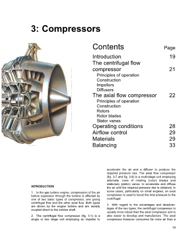
3: Compressors


                                                              Contents                                       Page


                                                              Introduction                                      19
                                                              The centrifugal flow

                                                              compressor                                        21

                                                                 Principles of operation
                                                                 Construction
                                                                 Impellers
                                                                 Diffusers
                                                              The axial flow compressor                         22
                                                                 Principles of operation
                                                                 Construction
                                                                 Rotors
                                                                 Rotor blades
                                                                 Stator vanes
                                                              Operating conditions                              28

                                                              Airflow control                                   29

                                                              Materials                                         29
                                                              Balancing                                         33


                                                                       accelerate the air and a diffuser to produce the
                                                                       required pressure rise.  The axial flow compressor
                                                                       (fig. 3-7 and fig. 3-8) is a multi-stage unit employing
                                                                       alternate .rows of rotating (rotor) blades and
                                                                       stationary (stator) vanes, to accelerate and diffuse
                      INTRODUCTION                                     the air until the required pressure rise is obtained. In
                      1. In the gas turbine engine, compression of the air  some cases, particularly on small engines, an axial
                      before expansion through the turbine is effected by  compressor is used to boost the inlet pressure to the
                      one of two basic types of compressor, one giving  centrifugal.
                      centrifugal flow and the other axial flow. Both types
                      are driven by the engine turbine and are usually  3. With regard to the advantages and disadvan-
                      coupled direct to the turbine shaft.             tages of the two types, the centrifugal compressor is
                                                                       usually more robust than the axial compressor and is
                      2. The centrifugal flow compressor (fig. 3-1) is a  also easier to develop and manufacture. The axial
                      single or two stage unit employing an impeller to  compressor however consumes far more air than a

                                                                                                                  19