
Page 32 - The Jet Engine
P. 32
Compressors
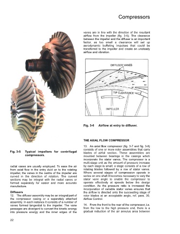
vanes are in line with the direction of the resultant
airflow from the impeller (fig. 3-6). The clearance
between the impeller and the diffuser is an important
factor, as too small a clearance will set up
aerodynamic buffeting impulses that could be
transferred to the impeller and create an unsteady
airflow and vibration.
Fig. 3-6 Airflow at entry to diffuser.
THE AXIAL FLOW COMPRESSOR
13. An axial flow compressor (fig. 3-7 and fig. 3-8)
consists of one or more rotor assemblies that carry
Fig. 3-5 Typical impellers for centrifugal blades of airfoil section. These assemblies are
compressors. mounted between bearings in the casings which
incorporate the stator vanes. The compressor is a
multi-stage unit as the amount of pressure increase
radial vanes are usually employed. To ease the air by each stage is small; a stage consists of a row of
from axial flow in the entry duct on to the rotating rotating blades followed by a row of stator vanes.
impeller, the vanes in the centre of the impeller are Where several stages of compression operate in
curved in the direction of rotation. The curved series on one shaft it becomes necessary to vary the
sections may be integral with the radial vanes or stator vane angle to enable the compressor to
formed separately for easier and more accurate operate effectively at speeds below the design
manufacture. condition. As the pressure ratio is increased the
incorporation of variable stator vanes ensures that
Diffusers the airflow is directed onto the succeeding stage of
12. The diffuser assembly may be an integral part of rotor blades at an acceptable angle, ref. para. 30,
the compressor casing or a separately attached Airflow Control.
assembly. In each instance it consists of a number of
vanes formed tangential to the impeller. The vane 14. From the front to the rear of the compressor, i.e.
passages are divergent to convert the kinetic energy from the low to the high pressure end, there is a
into pressure energy and the inner edges of the gradual reduction of the air annulus area between
22