
Page 36 - The Jet Engine
P. 36
Compressors
removed at an intermediate stage and .dumped into
the bypass flow. While this method corrects the axial
velocity through the preceding stages, energy is
wasted and incorporation of variable stators is
preferred.
22. The fan of the high by-pass ratio turbo-fan is an
example of an axial compressor which has been
optimized to meet the specific requirements of this
cycle. While similar in principle to the core
compressor stage, the proportions of design are
such that the inner gas path is similar to that of the
core compressor that follows it, while the tip diameter
is considerably larger. The mass flow passed by the
fan is typically six times that required by the core, the
remaining five sixths by-pass the core and is
expanded through its own coaxial nozzle, or may be
mixed with the flow at exit from the core in a common
nozzle. To optimize the cycle the by-pass flow has to
be raised to a pressure of approximately 1.6 times
the inlet pressure. This is achieved in the fan by
utilizing very high tip speeds (1500 ft. per sec.) and
airflow such that the by-pass section of the blades
operate with a supersonic inlet air velocity of up to
Mach 1.5 at the tip. The pressure that results is
graded from a high value at the tip where relative
velocities are highest to the more normal values of
1.3 to 1.4 at the inner radius which supercharges the
core where aerodynamic design is more akin to that
of a conventional compressor stage. The capability
of this type of compressor stage achieves the cycle
requirement of high flow per unit of frontal area, high
efficiency and high pressure ratio in a single rotating
blade row without inlet guide vanes within an
acceptable engine diameter. Thus keeping weight
and mechanical complexity at an acceptable level.
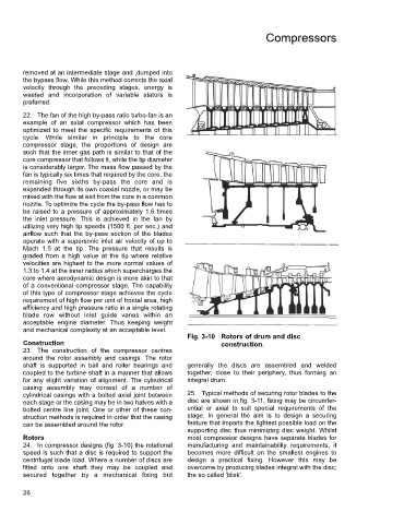
Fig. 3-10 Rotors of drum and disc
Construction construction.
23. The construction of the compressor centres
around the rotor assembly and casings. The rotor
shaft is supported in ball and roller bearings and generally the discs are assembled and welded
coupled to the turbine shaft in a manner that allows together, close to their periphery, thus forming an
for any slight variation of alignment. The cylindrical integral drum.
casing assembly may consist of a number of
cylindrical casings with a bolted axial joint between 25. Typical methods of securing rotor blades to the
each stage or the casing may be in two halves with a disc are shown in fig. 3-11, fixing may be circumfer-
bolted centre line joint. One or other of these con- ential or axial to suit special requirements of the
struction methods is required in order that the casing stage. In general the aim is to design a securing
can be assembled around the rotor. feature that imparts the lightest possible load on the
supporting disc thus minimizing disc weight. Whilst
Rotors most compressor designs have separate blades for
24. In compressor designs (fig. 3-10) the rotational manufacturing and maintainability requirements, it
speed is such that a disc is required to support the becomes more difficult on the smallest engines to
centrifugal blade load. Where a number of discs are design a practical fixing. However this may be
fitted onto one shaft they may be coupled and overcome by producing blades integral with the disc;
secured together by a mechanical fixing but the so called 'blisk'.
26