
Page 35 - The Jet Engine
P. 35
Compressors
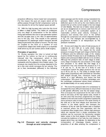
propulsive efficiency, hence lower fuel consumption. stator passage and the kinetic energy translated into
For this reason the pure jet engine where all the pressure. Stator vanes also serve to correct the
airflow passes through the full compression cycle is deflection given to the air by the rotor blades and to
now obsolete for all but the highest speed aircraft. present the air at the correct angle to the next stage
of rotor blades. The last row of stator vanes usually
18. With the high by-pass ratio turbo-fan this trend act as air straighteners to remove swirl from the air
is taken a stage further. The intake air undergoes prior to entry into the combustion system at a
only one stage of compression in the fan before reasonably uniform axial velocity. Changes in
being split between the core or gas generator system pressure and velocity that occur in the airflow
and the by-pass duct in the ratio of approximately through the compressor are shown diagrammatically
one to five (fig. 3-8). This results in the optimum in fig. 3-9. The changes are accompanied by a
arrangement for passenger and/or transport aircraft progressive increase in air temperature as the
flying at just below the speed of sound. The fan may pressure increases.
be coupled to the front of a number of core
compression stages (two shaft engine) or a separate 20. Across each stage the ratio of total pressures of
shaft driven by its own turbine (three shaft engine). outgoing air and inlet air is quite small, being
between 1:1 and 1:2. The reason for the small
Principles of operation pressure increase through each stage is that the rate
19. During operation the rotor is turned at high of diffusion and the deflection angle of the .blades
speed by the turbine so that air is continuously must be limited if losses due to air breakaway at the
induced into the compressor, which is then blades and subsequent blade stall are to be avoided.
accelerated by the rotating blades and swept Although the pressure ratio of each stage is small,
rearwards onto the adjacent row of stator vanes. The every stage increases the exit pressure of the stage
pressure rise results from the energy imparted to the that precedes it. So whilst this first stage of a
air in the rotor which increases the air velocity. The compressor may only increase the pressure by 3 to
air is then decelerated (diffused) in the following 4 lb. per sq. in., at the rear of a thirty to one
compression system the stage pressure rise can be
up to 80 lb, per sq. in, The ability to design multi-
stage axial compressors with controlled air velocities
and straight through flow, minimizes losses and
results in a high efficiency and hence low fuel
consumption. This gives it a further advantage over
the centrifugal compressor where these conditions
are fundamentally not so easily achieved.
21. The more the pressure ratio of a compressor is
increased the more difficult it becomes to ensure that
it will operate efficiently over the full speed range.
This is because the requirement for the ratio of inlet
area to exit area, at the high speed case, results in
an inlet area that becomes progressively too large
relative to the exit area as the compressor speed and
hence pressure ratio is reduced. The axial velocity of
the inlet air in the front stages thus becomes low
relative to the blade speed, this changes the
incidence of the air onto the blades and a condition
is reached where the flow separates and the
compressor flow breaks down. Where high pressure
ratios are required from a single compressor this
problem can be overcome by introducing variable
stator vanes in the front stages of the system. This
corrects the incidence of air onto the rotor blades to
angles which they can tolerate. An alternative is the
Fig. 3-9 Pressure and velocity changes incorporation of interstage bleeds, where a
through an axial compressor. proportion of air after entering the compressor is
25