
Page 39 - The Jet Engine
P. 39
Compressors
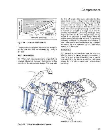
the form of variable inlet guide vanes for the first
stage plus a number of stages incorporating variable
stator vanes for the succeeding stages as the shaft
pressure ratio is increased (fig. 3-15). As the
compressor speed is reduced from its design value
these static vanes are progressively closed in order
to maintain an acceptable air angle value onto the
following rotor blades. Additionally interstage bleed
may be provided but its use in design is now usually
limited to the provision of extra margin while the
engine is being accelerated, because use at steady
operating conditions is inefficient and wasteful of
Fig. 3-14 Limits of stable airflow. fuel. Three types of air bleed systems are illustrated
as follows: fig. 3-16 hydraulic, fig. 3-17 pneumatic
and fig. 3-18 electronic.
Compressors are designed with adequate margin to
ensure that this area of instability (fig. 3-14) is MATERIALS
avoided.
31. Materials are chosen to achieve the most cost
AIRFLOW CONTROL effective design for the components in question, in
practice for aero engine design this need is usually
30. Where high pressure ratios on a single shaft are best satisfied by the lightest design that technology
required it becomes necessary to introduce airflow allows for the given loads and temperatures
control into the compressor design. This may take prevailing.
Fig. 3-15 Typical variable stator vanes.
29