
Page 48 - The Jet Engine
P. 48
Combustion chambers
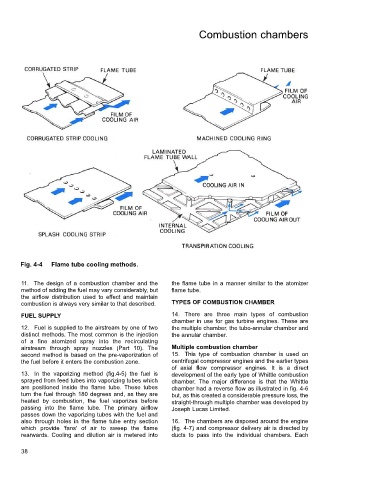
Fig. 4-4 Flame tube cooling methods.
11. The design of a combustion chamber and the the flame tube in a manner similar to the atomizer
method of adding the fuel may vary considerably, but flame tube.
the airflow distribution used to effect and maintain
combustion is always very similar to that described. TYPES OF COMBUSTION CHAMBER
FUEL SUPPLY 14. There are three main types of combustion
chamber in use for gas turbine engines. These are
12. Fuel is supplied to the airstream by one of two the multiple chamber, the tubo-annular chamber and
distinct methods. The most common is the injection the annular chamber.
of a fine atomized spray into the recirculating
airstream through spray nozzles (Part 10). The Multiple combustion chamber
second method is based on the pre-vaporization of 15. This type of combustion chamber is used on
the fuel before it enters the combustion zone. centrifugal compressor engines and the earlier types
of axial flow compressor engines. It is a direct
13. In the vaporizing method (fig.4-5) the fuel is development of the early type of Whittle combustion
sprayed from feed tubes into vaporizing tubes which chamber. The major difference is that the Whittle
are positioned inside the flame tube. These tubes chamber had a reverse flow as illustrated in fig. 4-6
turn the fuel through 180 degrees and, as they are but, as this created a considerable pressure loss, the
heated by combustion, the fuel vaporizes before straight-through multiple chamber was developed by
passing into the flame tube. The primary airflow Joseph Lucas Limited.
passes down the vaporizing tubes with the fuel and
also through holes in the flame tube entry section 16. The chambers are disposed around the engine
which provide 'fans' of air to sweep the flame (fig. 4-7) and compressor delivery air is directed by
rearwards. Cooling and dilution air is metered into ducts to pass into the individual chambers. Each
38