
Page 47 - The Jet Engine
P. 47
Combustion chambers
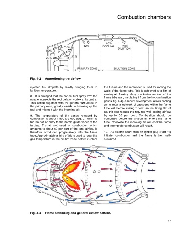
Fig. 4-2 Apportioning the airflow.
injected fuel droplets by rapidly bringing them to the turbine and the remainder is used for cooling the
ignition temperature. walls of the flame tube. This is achieved by a film of
cooling air flowing along the inside surface of the
8. It is arranged that the conical fuel spray from the flame tube wall, insulating it from the hot combustion
nozzle intersects the recirculation vortex at its centre. gases (fig. 4-4). A recent development allows cooling
This action, together with the general turbulence in air to enter a network of passages within the flame
the primary zone, greatly assists in breaking up the
fuel and mixing it with the incoming air. tube wall before exiting to form an insulating film of
air, this can reduce the required wall cooling airflow
9. The temperature of the gases released by by up to 50 per cent. Combustion should be
combustion is about 1,800 to 2,000 deg. C., which is completed before the dilution air enters the flame
far too hot for entry to the nozzle guide vanes of the tube, otherwise the incoming air will cool the flame
turbine. The air not used for combustion, which and incomplete combustion will result.
amounts to about 60 per cent of the total airflow, is
therefore introduced progressively into the flame 10. An electric spark from an igniter plug (Part 11)
tube. Approximately a third of this is used to lower the initiates combustion and the flame is then self-
gas temperature in the dilution zone before it enters sustained.
Fig. 4-3 Flame stabilizing and general airflow pattern.
37