
Page 77 - The Jet Engine
P. 77
Accessory drives
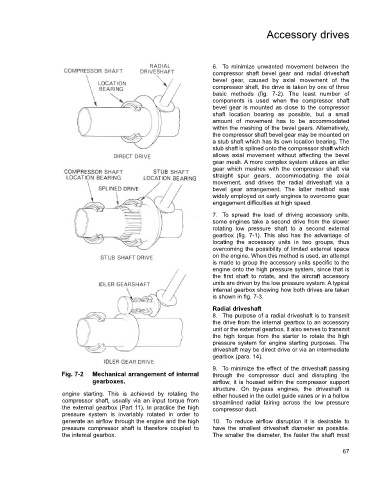
6. To minimize unwanted movement between the
compressor shaft bevel gear and radial driveshaft
bevel gear, caused by axial movement of the
compressor shaft, the drive is taken by one of three
basic methods (fig. 7-2). The least number of
components is used when the compressor shaft
bevel gear is mounted as close to the compressor
shaft location bearing as possible, but a small
amount of movement has to be accommodated
within the meshing of the bevel gears. Alternatively,
the compressor shaft bevel gear may be mounted on
a stub shaft which has its own location bearing. The
stub shaft is splined onto the compressor shaft which
allows axial movement without affecting the bevel
gear mesh. A more complex system utilizes an idler
gear which meshes with the compressor shaft via
straight spur gears, accommodating the axial
movement, and drives the radial driveshaft via a
bevel gear arrangement. The latter method was
widely employed on early engines to overcome gear
engagement difficulties at high speed.
7. To spread the load of driving accessory units,
some engines take a second drive from the slower
rotating low pressure shaft to a second external
gearbox (fig. 7-1). This also has the advantage of
locating the accessory units in two groups, thus
overcoming the possibility of limited external space
on the engine. When this method is used, an attempt
is made to group the accessory units specific to the
engine onto the high pressure system, since that is
the first shaft to rotate, and the aircraft accessory
units are driven by the low pressure system. A typical
internal gearbox showing how both drives are taken
is shown in fig. 7-3.
Radial driveshaft
8. The purpose of a radial driveshaft is to transmit
the drive from the internal gearbox to an accessory
unit or the external gearbox. It also serves to transmit
the high torque from the starter to rotate the high
pressure system for engine starting purposes. The
driveshaft may be direct drive or via an intermediate
gearbox (para. 14).
9. To minimize the effect of the driveshaft passing
Fig. 7-2 Mechanical arrangement of internal through the compressor duct and disrupting the
gearboxes. airflow, it is housed within the compressor support
structure. On by-pass engines, the driveshaft is
engine starting. This is achieved by rotating the either housed in the outlet guide vanes or in a hollow
compressor shaft, usually via an input torque from streamlined radial fairing across the low pressure
the external gearbox (Part 11). In practice the high compressor duct.
pressure system is invariably rotated in order to
generate an airflow through the engine and the high 10. To reduce airflow disruption it is desirable to
pressure compressor shaft is therefore coupled to have the smallest driveshaft diameter as possible.
the internal gearbox. The smaller the diameter, the faster the shaft must
67