
Page 73 - The Jet Engine
P. 73
Exhaust system
8. The propelling nozzle size is extremely important
and must be designed to obtain the correct balance
of pressure, temperature and thrust. With a small
nozzle these values increase, but there is a
possibility of the engine surging (Part 3), whereas
with a large nozzle the values obtained are too low,
9. A fixed area propelling nozzle is only efficient
over a narrow range of engine operating conditions.
To increase this range, a variable area nozzle may
be used. This type of nozzle is usually automatically
controlled and is designed to maintain the correct
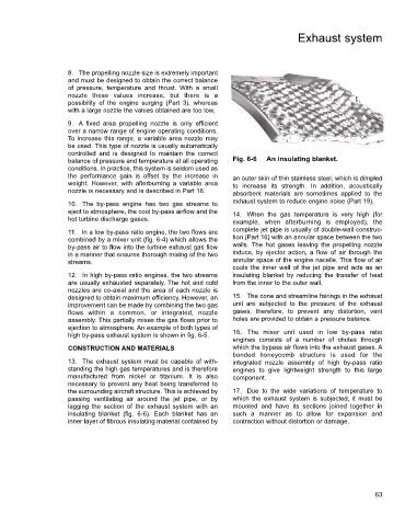
balance of pressure and temperature at all operating Fig. 6-6 An insulating blanket.
conditions. In practice, this system is seldom used as
the performance gain is offset by the increase in an outer skin of thin stainless steel, which is dimpled
weight. However, with afterburning a variable area to increase its strength. In addition, acoustically
nozzle is necessary and is described in Part 16. absorbent materials are sometimes applied to the
exhaust system to reduce engine noise (Part 19).
10. The by-pass engine has two gas streams to
eject to atmosphere, the cool by-pass airflow and the 14. When the gas temperature is very high (for
hot turbine discharge gases. example, when afterburning is employed), the
11. In a low by-pass ratio engine, the two flows are complete jet pipe is usually of double-wall construc-
combined by a mixer unit (fig. 6-4) which allows the tion (Part 16) with an annular space between the two
by-pass air to flow into the turbine exhaust gas flow walls. The hot gases leaving the propelling nozzle
in a manner that ensures thorough mixing of the two induce, by ejector action, a flow of air through the
streams. annular space of the engine nacelle. This flow of air
cools the inner wall of the jet pipe and acts as an
12. In high by-pass ratio engines, the two streams insulating blanket by reducing the transfer of heat
are usually exhausted separately. The hot and cold from the inner to the outer wall.
nozzles are co-axial and the area of each nozzle is
designed to obtain maximum efficiency. However, an 15. The cone and streamline fairings in the exhaust
improvement can be made by combining the two gas unit are subjected to the pressure of the exhaust
flows within a common, or integrated, nozzle gases; therefore, to prevent any distortion, vent
assembly. This partially mixes the gas flows prior to holes are provided to obtain a pressure balance.
ejection to atmosphere. An example of both types of
high by-pass exhaust system is shown in fig, 6-5. 16. The mixer unit used in low by-pass ratio
engines consists of a number of chutes through
CONSTRUCTION AND MATERIALS which the bypass air flows into the exhaust gases. A
bonded honeycomb structure is used for the
13. The exhaust system must be capable of with- integrated nozzle assembly of high by-pass ratio
standing the high gas temperatures and is therefore engines to give lightweight strength to this large
manufactured from nickel or titanium. It is also component.
necessary to prevent any heat being transferred to
the surrounding aircraft structure. This is achieved by 17. Due to the wide variations of temperature to
passing ventilating air around the jet pipe, or by which the exhaust system is subjected, it must be
lagging the section of the exhaust system with an mounted and have its sections joined together in
insulating blanket (fig. 6-6). Each blanket has an such a manner as to allow for expansion and
inner layer of fibrous insulating material contained by contraction without distortion or damage.
63