
Page 141 - The Master Handbook Of Acoustics
P. 141
116 CHAPTER FIVE
The total harmonic distortion (THD) may then be found from the
expression:
(e ) (e ) (e ) … (e ) 2
2
2
2
3
2
4
n
THD 100 (5-1)
e
o
where e , e , e …e voltages of 2nd, 3rd, 4th, etc. harmonics
2 3 4 n
e voltage of fundamental
o
In Table 5-2 the harmonic voltages have been squared and added
together reducing Eq. 5-1 to:
0.143 125
THD 100
1.00
Undistorted sine wave 37.8%
A total harmonic distortion of 37.8% is a
very high distortion that would make any
amplifier sound horrible on any type of
signal, but the example has served our
purpose in illustrating just what THD is
Positive peaks clipped
and one method for obtaining it.
5% THD 10% THD
Wave analyzers are expensive, high-
precision instruments that are rarely
found in equipment service shops. A
very simple adaptation of the THD
method is, however, widely used. Con-
sider Fig. 5-20 again. If the f fundamen-
This is what the harmonics look like on the cathode o
ray oscilloscope to the same scales as above. tal were adjusted to some known value
and then a notch filter were adjusted to f
o
essentially eliminating it, only the har-
monics would be left. Measuring these
harmonics all lumped together with an
FIGURE 5-21 RMS (root mean square) meter, accom-
plishes what was done in the square root
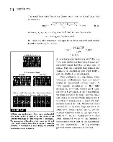
Cathode ray oscillograms show pure, undistorted
sine wave, which is applied to the input of an portion of Eq. 5-1. Comparison of this
amplifer that clips the positive peaks of the signal. RMS measured value of the harmonic
The appearance of the clipped sine wave for 5% and components with that of the fundamen-
10% total harmonic distortion is shown. If the fun- tal and expressing it as a percentage
damental is rejected by a notch filter, the summed
harmonics appear as shown. gives the total harmonic distortion.