Page 146 - The Master Handbook Of Acoustics
P. 146

121
                                                                ANALOG AND DIGITAL SIGNAL PROCESSING


                      effect of a capacitance. Figure 6-2 shows
                      the symbols for inductance (L), commonly                      L
                      a coil of wire, and capacitance (C), com-
                      monly made of sheets of conducting mate-
                      rial separated by nonconducting sheets.
                      Energy can be stored in the magnetic field
                      of an inductance as well as in the electrical
                      charges on the plates of a capacitance. The
                      interchange of energy between two such                        C
                      storage systems can result in a resonance
                      effect. Perhaps, the simplest example of
                      this is a weight on a spring.
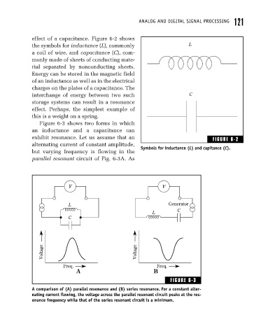
                         Figure 6-3 shows two forms in which
                      an inductance and a capacitance can
                      exhibit resonance. Let us assume that an                               FIGURE 6-2
                      alternating current of constant amplitude,
                                                                 Symbols for inductance (L) and capitance (C).
                      but varying frequency is flowing in the
                      parallel resonant circuit of Fig. 6-3A. As


                                    V                                    V


                                    L                                       Generator
                                                                               C
                                                                     L
                                    C


                          Voltage                              Voltage


                                  Freq.                                Freq.
                                       A                              B

                                                                             FIGURE 6-3
                      A comparison of (A) parallel resonance and (B) series resonance. For a constant alter-
                      nating current flowing, the voltage across the parallel resonant circuit peaks at the res-
                      onance frequency while that of the series resonant circuit is a minimum.
   141   142   143   144   145   146   147   148   149   150   151