
Page 147 - The Master Handbook Of Acoustics
P. 147
122 CHAPTER SIX
the frequency is varied, the voltage at the terminals reaches a maxi-
mum at the natural frequency of the LC system, falling off at lower and
higher frequencies. In this way the typical resonance curve shape is
developed. Another way of saying this is that the parallel resonant cir-
cuit exhibits maximum impedance (opposition to the flow of current)
at resonance.
Figure 6-3B illustrates the series resonant arrangement of an
inductance L and a capacitance C. As the alternating current of con-
stant magnitude and varying frequency flows in the circuit, the volt-
age at the terminals describes an inverted resonance curve in which
the voltage is minimum at the natural frequency and rising at both
lower and higher frequencies. It can also be said that the series res-
onant circuit presents minimum impedance at the frequency of res-
onance.
Filters
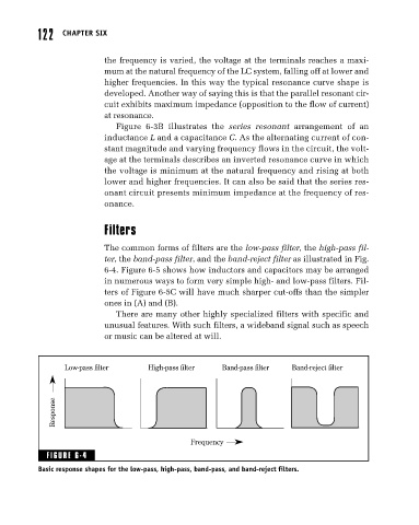
The common forms of filters are the low-pass filter, the high-pass fil-
ter, the band-pass filter, and the band-reject filter as illustrated in Fig.
6-4. Figure 6-5 shows how inductors and capacitors may be arranged
in numerous ways to form very simple high- and low-pass filters. Fil-
ters of Figure 6-5C will have much sharper cut-offs than the simpler
ones in (A) and (B).
There are many other highly specialized filters with specific and
unusual features. With such filters, a wideband signal such as speech
or music can be altered at will.
Low-pass filter High-pass filter Band-pass filter Band-reject filter
Response
Frequency
FIGURE 6-4
Basic response shapes for the low-pass, high-pass, band-pass, and band-reject filters.