
Page 233 - The Master Handbook Of Acoustics
P. 233
208 CHAPTER NINE
0.8
0.6 C
Absorption coefficient 0.4 B
0.2 A
0
100 1,000 4,000
Frequency - Hz
FIGURE 9-22
3
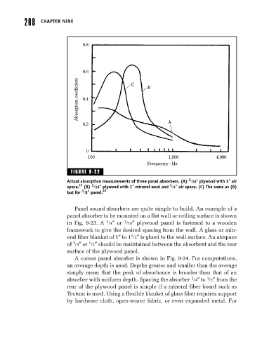
Actual absorption measurements of three panel absorbers. (A) 16″ plywood with 2″ air
19 1 1
space. (B) 16″ plywood with 1″ mineral wool and 4″ air space. (C) The same as (B)
1
but for 8″ panel. 20
Panel sound absorbers are quite simple to build. An example of a
panel absorber to be mounted on a flat wall or ceiling surface is shown
1
1
in Fig. 9-23. A 4″ or 16″ plywood panel is fastened to a wooden
framework to give the desired spacing from the wall. A glass or min-
1
eral fiber blanket of 1″ to 1 2″ is glued to the wall surface. An airspace
1
1
of 4″ or 2″ should be maintained between the absorbent and the rear
surface of the plywood panel.
A corner panel absorber is shown in Fig. 9-24. For computations,
an average depth is used. Depths greater and smaller than the average
simply mean that the peak of absorbance is broader than that of an
1
1
absorber with uniform depth. Spacing the absorber 4″ to 2″ from the
rear of the plywood panel is simple if a mineral fiber board such as
Tectum is used. Using a flexible blanket of glass fiber requires support
by hardware cloth, open-weave fabric, or even expanded metal. For