
Page 237 - The Master Handbook Of Acoustics
P. 237
212 CHAPTER NINE
feature will become more apparent as the actual acoustical design of
listening rooms and studios is approached.
Poly Construction
The construction of polycylindrical diffusers is reasonably simple. A
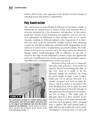
framework for vertical polys is shown in Fig. 9-26 mounted above a
structure intended for a low-frequency slat absorber. In this photo-
graph the variable chord dimensions are apparent, and also the ran-
dom placement of bulkheads so that cavities will be of various
volumes resulting in different natural cavity frequencies. It is desir-
able that each cavity be essentially airtight, isolated from adjoining
cavities by well-fitted bulkheads and framework. Irregularities in the
wall can be sealed with a nonhardening acoustical sealant. The bulk-
heads of each poly are carefully cut to the same radius on a bandsaw.
Sponge rubber weatherstripping with an adhesive on one side is
struck to the edge of each bulkhead to ensure a tight seal against the
plywood or hardboard cover. If such precautions are not taken, annoy-
ing rattles and coupling between cavities can result.
1
The polys of Fig. 9-26 use 8″ tempered
Masonite as the poly skin. A few hints can
simplify the job of stretching this skin. In
Fig. 9-27 slots of a width to fit the
Masonite snugly are carefully cut along
the entire length of strips 1 and 2 with a
radial saw. Let us assume that poly A is
already mounted and held in place by
strip 1, which is nailed or screwed to the
wall. Working from left to right, the next
job is to mount poly B. First the left edge of
Masonite sheet B is inserted in the remain-
ing slot of strip 1. The right edge of
FIGURE 9-26 Masonite sheet B is then inserted in the
The construction of polys in a motion picture sound left slot of strip 2. If all measurements and
mixing studio. Note the foam rubber anti-rattle strip cuts have been accurately made, swinging
on the edge of each bulkhead. Also note the random strip 2 against the wall should make a
spacing of the bulkheads. (Moody Institute of Science
photo, reprinted with permission of the Journal of the tight seal over the bulkheads 3 and weath-
21
Audio Engineering Society. ) erstripping 4. Securing strip 2 to the wall