
Page 161 - The Petroleum System From Source to Trap
P. 161
154 Jordan and Wilson
• DOLOMITIZATION 4> (a) Depth
o DISSOLUTION 4>
INNER SHELF FAIRWAY o BEACH DEPOSITS
• FRINGING REEFS
SB2 o TIDAL FLAT DEPOSITS OliTER SHELF FAIRWAY
•REEFS
:��������������������I!�������� • DISSOLLJTIOt# J:
• NEAR-REEF DEPOSITS
mfs - 7 oSHOALS T
• EXPOSURE SURFACES
SB 1
PINNACLE REEFS
Cl.
UTHOFACIES LEGEND POTENTIAl. SITE of 1-
w
ATOLLS� C
INNER SHELF ..,....,.....,....,.�
XG �ss mBc M Me
r.tDDLESHELF r-_..�====aiiiliiii D����s---. 1
XW/P lXW OSH X•P/G
Mlh locaized XG •G 0G
or OB �Betc.
OliTER SHELF
0G JIG •G �G X•G X•P
or 08 �B etc. L..:....:..-...:J
SLOPE
M/)..W
BASIN coarse BR (b) Geologic time
UNCONFORMITY
T
SM'N
SB2
w
HST ::2:
mfs CONDENSED i=
SECTION TST 0
a
SUBAERIAL HIATUS LST g
0
w
C!)
HST
1
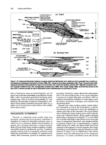
Figure 7.14. Carbonate lithofacies patterns and generalized reef distribution (a) in depth and (b) in geologic time, overlain on
the sequence stratigraphic framework of 5arg (1988). 581, sequence boundary associated with a Type 1 unconformity; 582,
sequence boundary associated with a type 2 unconformity; mfs, maximum flooding surface; H5T, highstand systems tract,
L5T, lowstand systems tract, TST, transgressive systems tract, 5MW, shelf margin wedge. Major unconformity surface at the
top of 581 is where porosity< + > due to dissolution and/or dolomitization is most likely to occur.
tions of fossil-poor zones are treated logically; and (3) secondary, formed by various dissolution mechanisms.
logical and somewhat predictable progradations of facies One of the main debates today is how much dissolution
belts, useful for prospect generation involving strati is produced at depth (Mazzullo and Harris, 1992) by
graphic traps. There is, however, the possibility of "over reactions involving the formation of weak organic acids,
applying" the principles of sequence stratigraphy to situ the thermal maturation of kerogen, and reactants from
ations where lateral correlations cannot be made (e.g., a dewatering shales.
single core 10m long from a rank wildcat well), usually Because rock-water reactions mainly control carbon
due to a lack of data. ate cementation as well as the development of dissolu
tion porosity, it is important to know the distribution of
various pore fluids in the subsurface. The typical distrib
DIAGENETIC OVERPRINT ution of freshwater lenses, mixing zones, marine phreatic
zones, and "subsurface brines" along a typical carbonate
Porosity in carbonate rocks results from two shelf profile is summarized in Figure 7.15. A well drilled
processes: preservation from primary conditions of into a middle shelf high on this profile would encounter
deposition or creation by dissolution processes, many of zones of cementation, dissolution, and chemical stability
which occur at relatively shallow burial depths. In or inactivity (Figure 7.16), as summarized by Longman
general, few carbonate reservoirs-the giant Jurassic (1980), Harris et al. (1985), and Moore (1989). Since most
fields of Saudi Arabia being notable exceptions-display carbonate rocks originate as marine deposits, their diage
unmodified primary intergranular porosity. If primary netic history can be plotted, using the theoretical consid
porosity remains at all, it is commonly reduced to some erations of Figure 7.16, by beginning in the marine
degree by cementation, for example, by isopachous rim phreatic zone and following one of two diagenetic
cement. More commonly, porosity in carbonate rocks is pathways: (1) steady subsidence from the marine