
Page 48 -
P. 48
................................................................. Pump Hydraulics
the difference between operating the pump on a water service, and the
operation of the same pump on either a viscous liquid or on paper
stock. With viscous liquids, the performance gradually drops off to a
point where positive displacement pumps have to be introduced.
On paper stock with a consistency up to 3%, the pump will perform as
though it's handling water. Between 3% and about 6%, the adjustments
shown will come into effect. Above 6% consistency the centrifugal
pump may require some modifications depending on the fluidity of the
stock and the ability of the system to deliver it freely to the impeller.
With higher consistencies, a positive displacement screw pump is
usually used.
Further details on these and on slurry applications (which can also
include a viscous component) can be found in Chapter 8.
2.5 Impeller hydraulic loads
In an earlier section of this chapter, we identified that the Best
Efficiency Point (BEP) is the most stable operating condition for that
pump and is a direct result of the criteria used in that pump's design.
These criteria include the hydraulic loads that act on the pump impeller.
As they more directly relate to the pump bearings, the axial hydraulic
loads will be discussed in Chapter 7.2.
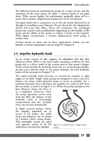
The radial hydraulic loads however, act around the impeller at right
angles to the shaft. Single volute pumps are designed in such a way as to
balance out these radial hydraulic loads as much as possible, but a
resultant hydraulic force will impact the impeller on a plane at 60 ~ from
the cut-water, as shown in Figure 2.12. When the pump operates at the
best efficiency point, this force is
at a minimum. However, when
the pump operation moves away
from the B EP, the balance of the
hydraulic loads is increasingly
compromised and the resultant
force can increase dramatically.
In larger process pumps, where
the impeller diameters are in
excess of 13 inches, the radial
forces are balanced out by means
of a double volute casing design.
This essentially creates an equal
and opposite action of all the Figure 2.12: Radial forces in single volute
radial forces around the impeller. casing
....... ~ ~ ~ ~ 27 ~
_ - ...... u ~!~.~]~ ~_ .............................. ~_ .