
Page 50 -
P. 50
.................................................................................................................................... Pump Hydraulics
From the above equation, it can be readily identified that the radial
force is at its maximum at the shut-off condition when Q = 0. As the
flow rate (Q) increases, the radial force decreases to a theoretical zero at
the B.E.P. When the flow exceeds the B.E.P., the radial force will
correspondingly increase, but as a negative value. This indicates that the
force is now acting in the opposite direction from that indicated in
Figure 2.12.
In the absence of any test data and, as a rough estimate only, the value
of the exponent (x) may be assumed to vary linearly between 0.7 at an
impeller specific speed of 500, and a value of 3.3 at an impeller specific
speed of 3,500. In a typical process pump it can be shown that the
impeller radial force developed at a capacity halfway between Shut-off
and the best efficiency point can be as high as 600 pounds.
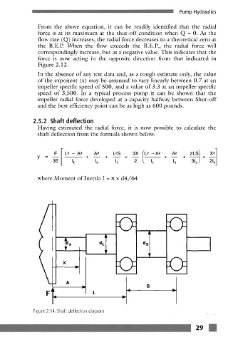
2.5.2 Shaft deflection
Having estimated the radial force, it is now possible to calculate the
shaft deflection from the formula shown below.
3X X]
= + + + + +
Y 3E IL I a I s 2 I L I a 3~) +
where Moment of Inertia I = = x d4/64
fl]
I v v
j
I:1 A ~ d
i
kLJ v v
X
Ft. "-I j- _,, J
i" "-I
Figure 2.14: Shaft deflection diagram
z9 R