
Page 85 -
P. 85
The Practical Pumping Handbook . . . . . . . . . . . . . . .
This condition can often be a result of pumping fermenting liquids or
foaming agents found in a wide variety of industries. It can also be a
result of pumping a liquid, such as condensate, that is close to its
boiling point.
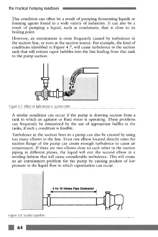
However, air entrainment is most frequently caused by turbulence in
the suction line, or even at the suction source. For example, the kind of
conditions identified in Figure 4.7, will cause turbulence in the suction
tank that will entrain vapor bubbles into the line leading from that tank
to the pump suction.
!iiii/ iili/iiiiiiiiiil
Figure 4.7: Effect of turbulence in suction tank
A similar condition can occur if the pump is drawing suction from a
tank in which an agitator or fluid mixer is operating. These problems
can frequently be minimized by the use of appropriate baffles in the
tanks, if such a condition is feasible.
Turbulence in the suction lines to a pump can also be created by using
too many elbows in the line. Even one elbow located directly onto the
suction flange of the pump can create enough turbulence to cause air
entrainment. If there are two elbows close to each other in the suction
piping in different planes, the liquid will exit the second elbow in a
swirling fashion that will cause considerable turbulence. This will create
an air entrainment problem for the pump by causing pockets of low
pressure in the liquid flow in which vaporization can occur.
i q5 to 10 times Pipe Diameter i
-[
Figure 4.8: Suction pipeline