
Page 86 -
P. 86
Suction Conditions
The ideal situation is to provide the suction side with a straight run of
pipe, in a length equivalent to 5 to 10 times the diameter of that pipe,
between the suction reducer and the first obstruction in the line. This
will ensure the delivery of a uniform flow of liquid to the eye of the
impcllcr and avoid any turbulence and air entrainment.
As air entrainment causes the same pitting damage to the impeller in
precisely the same location as cavitation, it can be a little confusing,
particularly as both can occur simultaneously in the same service.
However, a quick comparison of the NPSHA and NPSHR, combined
with a visual review of the piping characteristics will usually help
identify the root cause of the so-called 'cavitation' and solve the air
entrainment problem.
4.7 Similarities and differences
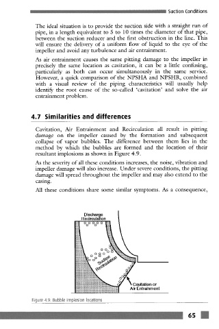
Cavitation, Air Entrainment and Recirculation all result in pitting
damage on the impeller caused by the formation and subsequent
collapse of vapor bubbles. The difference between them lies in the
method by which the bubbles are formed and the location of their
resultant implosions as shown in Figure 4.9.
As the severity of all these conditions increases, the noise, vibration and
impeller damage will also increase. Under severe conditions, the pitting
damage will spread throughout the impeller and may also extend to the
casing.
All these conditions share some similar symptoms. As a consequence,
Discharge
"i!i!
Figure 4.9: Bubble implosion locations
6s m