
Page 191 - The Tribology Handbook
P. 191
Friction clutches B7
~ ~~
CLUTCH SELECTION
A clutch is used to transmit motion from a power source to a driven component and bring the two to the same speed. Once
full engagement has been made, the clutch must usually be capable of transmitting, without slip, the maximum torque that
can be applied to it. The opera.ting characteristics ofthe various clutch designs, and the requirements ofthe application, can
be used as a guide to the selection of an appropriate type of clutch.
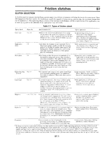
Table 7.1 Types of friction clutch
~ ~~~ ~~~
ope of clutch Figure No. Special characteristics Typical applications
Cone type 7.1, 7.2 Embodies the mechanical advantage of the wedge In general engineering its use is
which reduces the axial force required to transmit restricted to more rugged
a given torque. It also has greater facilities for heat applications such as contractors’
dissipation than a plate clutch of similar size and plant. Machine-tool applications
so may be more heavily rated include feed drives, and bar feed for
auto. lathes. (Figure 7.2)
Single-plate 7.3 Used where the diameter is not restricted. Coil or Wide applications in automobile and
(disc) diaphragm springs usually provide the clamping other traction drives. Figure 7.5 (a
pressure by forcing the spinner plate against the and b) show alternative operating
driving plate. Simple construction, and if of the methods
open type ensures no distortion of the spinner
plate by overheating
Multi-plate 7.4 Main feature is that the power transmitted can be Extensively used in machine tool
increased by using more plates, thus allowing a head-stocks, or in any gearbox drive
reduction in diameter. The spline friction should where space is limited between shaft
be minimised to ensure that clamping losses are centres. Figure 7.5(c) shows an
small, and that the working rates of all plates are operating method
as uniform as possible. If working in oil,* it must
be enclosed, whereas a dry plate clutch can often
have circulating air to carry away the heat
generated
~ ~~
Expanding ring 7.6, 7.7 Will transmit high torque at low speed. Centrifugal Large excavators. Textile machinery
or band force augments gripping power, so withdrawal drives. Machine tools where clutch is
force must be adequate. Both cases show positive located in main driving pulley
engagement
Centrifugal 7.8, 7.9 Automatic in operation, the torque without spring Wide applications on all types of
control increasing as the square of the speed. An electric motor drives, generally
electric motor with a low starting torque can reducing motor size and cost.
commence engagement without shock, the clutch Industrial dirscl engine drives
acting as a safety device against stalling and
overload. Shoes are often spring-loaded to prevent
engagement until 75% of full speed has been
reached
Magnetic 7.10, 7.1 1, 7.12 Units are compact, and operate by a direct magnet Drives with automatic speed-changing
pull through switch engagement. No end thrust is systems requiring remote control.
transmitted, and centrifiigal force has no effect on Machine tool gearboxes. N.C.
drive. Stock clutches are generally wound for 24 V machine tools. Tracer control
d.c. with powers up to about 37 kW at systems for copying
100 rev/min. The response curves, (Figure 7.12)
show typical torque and voltage time charts
~
Hydraulic 7.13 Clutches can be incorporated into automatic machine Marine reversing drives. Excavators.
cycles by remote control of solenoid valves. They Diesel turbine drives. Winch drives.
give high torque with minimum size, i.e. compared Presses
with magnetic clutches identical dimensions result
in a torque ratio of 3: 1. Maintenance low because
of working in oil, and piston stroke compensates
for wear
~~
Pneumatic Function similar to that of hydraulic clutch, Crank presses. Flying shear. Rolling
producing axial pressure by cylinder and piston. mill drives. Cranes. Hammers
General design is usually of the multi-disc type
* Working in oil gives a reduction in friction, but this can be counteracted by higher operating pressures. As fang as there is an oil
film on the plates, the friction and the engagement torque remain low, but as soon as the film breaks the engagement torque rises
rapidly and may lead to rapid acceleration. The friction surface pressure should not exceed I MN/m2 with a sliding speed
maximum of 20 m/s for steel on steel. With oil immersed clutches having steel and sintered plates, the relationship between static
and dynamic coellicient of friction is more favourable. Friction surface pressure and sliding speed may then be up to 3 MN/m2 and
30 mis.
B7.1