
Page 286 - The Tribology Handbook
P. 286
Mechanical seals B24
Power absorption and starting torque has been standing for a long time and corrosion (chemical
or electrolytic) has formed a chemical bond at the periph-
The coeficient of friction between the sea1 faces varies ery of the seal rings, which has to be broken before rotation
from a maximum dry value at zero product pressure to a can begin, the break-out torque may increase to many
minimum value in the region 0.7-1 MN/m2 (100-140 times (over 5 times) the normal starting torque. Che-
p.s.i.). It increases imperceptibly at higher product pres- mically inert seal faces-ceramic, glass-filled BTFE
sures. Over the normal range of pump speeds, power etc.-should then be used.
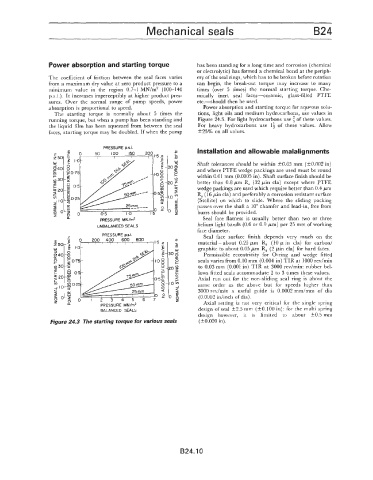
absorption is proportional to speed. Power absorption and starting torque for aqueous solu-
The starting torque is normally about 5 times the tions, light oils and medium hydrocarbons, use values in
running torque, but when a pump has been standing and Figure 24.3. For light hydrocarbons use $ of these values.
the liquid film has been squeezed from between the seal For heavy hydrocarbons use If of these values. Allow
faces, starting torque may be doubled. If when the pump +25% on all values.
PRESSURE ps.i
Installation and allowable malalignments
Shaft tolerances should be within 33.05 mm (k0.002 in)
and where PTFE wedge packings are used must be round
within 0.01 mm (0.0005 in). Shaft surface finish should be
better than 0.8 pm R, (32 pin cla) except where PTFE
wedge packings are used which require better than 0.4 pm
R, (16 pin cla) and preferably a corrosion resistant surface
(Stellite) on which to slide. Where the sliding packing
passes over the shaft a 10" chamfer and lead-in, free from
burrs should be provided.
n Seal face flatness is usually better than two or three
PRESSURE MN/rn2
UNBALANCED SEALS helium light bands (0.6 or 0.9 pm) per 25 mrn of working
face diameter.
Seal face surface finish depends very much on the
material - about 0.25 pm R, (10 p in cla) for carbon/
graphite to about 0.05 pm R, (2 pin cla) for hard faces.
Permissible eccentricity for O-ring and wedge fitted
seals varies from 0.10 mm (0.004 in) TIR at 1000 rev/rnin
to 0.03 mm (0.001 in) TIR at 3000 rev/min: rubber bei-
lows fitted seals accommodate 2 to 3 times these values.
Axial run out for the non-sliding seal ring is about the
same order as the above but for speeds higher than
3000 rev/min a useful guide is 0.0002 mm/mm of dia
(0.0002 idinch of dia).
"li PRESSURE MN/m2 Axial setting is not very critical for the single spring
BALANCED SEALS design of seal t2.5 mm (f0.100 in): for the multi spring
design however, it is limited to about k0.5 mrn
Figure 24.3 The starting torque for various seals (k0.020 in).
B24.10