
Page 291 - The Tribology Handbook
P. 291
_______~
B26 Mechanical piston rod packinqs
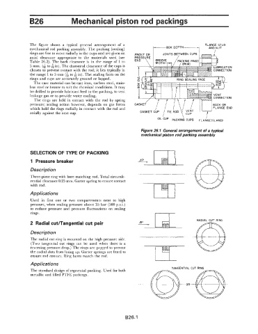
The figure shows a typical general arrangement of a FLANGE STUD
mechanical rod packing assembly. The packing (sealing)
rings are free to move radially in the cups and are given an
axial clearance appropriate to the materials used (see PRESS
Table 26.2). The back clearance is in the range of 1 to END
5 mm. (& to in). The diametral clearance of the cups is
chosen to prevent contact with the rod; it lies typically in
the range 1 to 5 mm (A to 6 in). The sealing faces on the
rings and cups are accurately ground or lapped.
The case material can be cast iron, carbon steel, stain-
less steel or bronze to suit the chemical conditions. It may
be drilled to provide lubricant feed to the packing, to vent
leakage gas or to provide water cooling.
The rings are held in contact with the rod by spring CONNECTION
pressure; sealing action however, depends on gas forces GASKE
which hold the rings radially in contact with the rod and
axially against the next cup.
Figure 26.1 General arrangement of a typical
mechanical piston rod packing assembly
SELECTION OF TYPE OF PACKING
1 Pressure breaker
Description
_~._______. .
Three-piece ring with bore matching rod. Total circumfe-
rential clearance 0.25 mm. Garter spring to ensure contact
with rod.
Applications
Used in first one or two compartments next to high
pressure, when sealing pressure above 35 bar (500 psi)
to reduce pressure and pressure fluctuations on sealing
rings.
RADIAL CUT RING
2 Radial cut/Tangential cut pair
Description
The radial cut ring is mounted on the high pressure side.
(Two tangential cut rings can be used when there is a
reversing pressure drop.) The rings are pegged to prevent
the radial slots from lining up. Garter springs are fitted to
ensure rod contact. Ring bores match the rod.
Applications
TANGENT 'IAL
The standard design of segmental packing. Used for both
metallic and filled PTFE packings.
OR
B26.1