
Page 256 - The Ultimate Palm Robot
P. 256
Color profile: Generic CMYK printer profile
Composite Default screen
Bots /The Ultimate Palm Robot/ Mukhar & Johnson / 222880-6 / Chapter 9
Chapter 9 Sensors and Enhancements 239
Adding Sensors to the BrainStem
With the BrainStem controller, we have a little more flexibility. The SV203 has
only analog input ports, the A/D ports in block J3 of the board. The BrainStem
has both A/D ports and digital ports. That means, of course, that we can use
the BrainStem for analog sensors and digital sensors or devices.
The BrainStem controller contains another port that you can use as well. This
is a GP2D02 port located between the digital ports and the servo ports. You can
connect another ranger directly to this port. Coincidentally, the name of this IR
Ranger is GP2D02. Alternatively, you can attach a special bus called an I2C bus.
With the I2C bus, you can connect up to 16 sonar rangers that can also detect
light, a compass module, and a text-to-speech module (SP03), all on the same
bus. Discussing the I2C bus further is beyond the scope of this book; however,
once you are familiar with the BrainStem, you may want to investigate using
the GP2D02 port and an I2C bus to attach other devices to the robot.
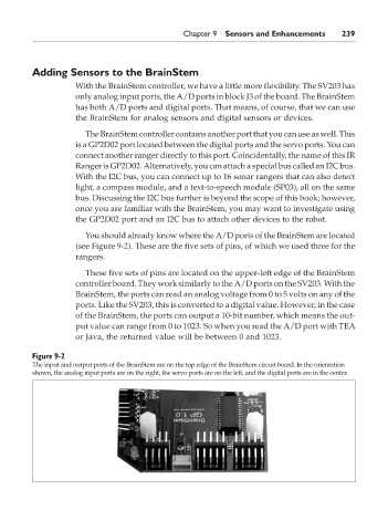
You should already know where the A/D ports of the BrainStem are located
(see Figure 9-2). These are the five sets of pins, of which we used three for the
rangers.
These five sets of pins are located on the upper-left edge of the BrainStem
controller board. They work similarly to the A/D ports on the SV203. With the
BrainStem, the ports can read an analog voltage from 0 to 5 volts on any of the
ports. Like the SV203, this is converted to a digital value. However, in the case
of the BrainStem, the ports can output a 10-bit number, which means the out-
put value can range from 0 to 1023. So when you read the A/D port with TEA
or Java, the returned value will be between 0 and 1023.
Figure 9-2
The input and output ports of the BrainStem are on the top edge of the BrainStem circuit board. In the orientation
shown, the analog input ports are on the right, the servo ports are on the left, and the digital ports are in the center.
P:\010Comp\Bots\880-6\ch09.vp
Monday, May 12, 2003 4:33:37 PM