
Page 102 - Welding of Aluminium and its Alloys
P. 102
Welding design 91
200
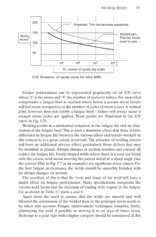
Unwelded. This line becomes asymptotic
150 Welded joint,
Stress,
N/mm 2 This line trends
100 down to zero
50
10 5 10 6 10 7 10 8
‘N’, number of cycles (log scale)
5.25 Stress/no. of cycles curve for alloy 5083.
Fatigue performance can be represented graphically on an S/N curve
where ‘S’ is the stress and ‘N’ the number of cycles to failure. For unwelded
components a fatigue limit is reached where below a certain stress failure
will not occur, irrespective of the number of cycles of stress it sees.A welded
joint, however, does not exhibit a fatigue limit – failure will always occur if
enough stress cycles are applied. These points are illustrated in the S/N
curve in Fig. 5.25.
Welding results in a substantial reduction in the fatigue life and an elim-
ination of the fatigue limit. This is such a dominant effect that there is little
difference in fatigue life between the various alloys and tensile strength in
this context is, to a great extent, irrelevant.The presence of welding defects
will have an additional adverse effect, particularly those defects that may
be classified as planar. Abrupt changes in section, notches and corners all
reduce the fatigue life. Poorly shaped welds where there is a poor toe blend
with the excess weld metal meeting the parent metal at a sharp angle (see
the convex fillet in Fig. 5.7 as an example) are significant stress raisers. For
the best fatigue performance the welds should be smoothly blended with
no abrupt changes on section.
The corollary of this is that the form and shape of the weld will have a
major effect on fatigue performance. Many specifications categorise the
various weld forms and the direction of loading with respect to the fatigue
life as shown in Table 5.1 parts a and b.
Apart from the need to ensure that the welds are smooth and well
blended the orientation of the welded item to the principal stress needs to
be taken into account. Fatigue improvement techniques comprise, firstly,
eliminating the weld if possible or moving it to an area of lower stress.
Redesign to a joint type with a higher category should be considered. If this