
Page 156 - The Mechatronics Handbook
P. 156
The rack and pinion example illustrates a basic method for relieving derivative causality, which can
be used to build basic energy-storing element models. Some problems might arise when the kinetic co-
energy depends on system configuration. In such a case, a more systematic method employing Lagrange’s
equations may be more suitable (see Section 9.7).
The approach described here for deriving constitutive relations is similar to Castigliano’s theorom [6,9].
Castigliano’s theorem relies on formulation of a strain-energy function in terms of the forces or moments,
and as such employs a potential co-energy function. Specifically, the results lead to displacements (trans-
lational, rotational) as functions of efforts (forces, torques). As in the case above, these functions are
found by taking partial derivatives of the co-energy with respect to force or moment. Castigliano’s theorem
is especially well-suited for finding force-displacment functions for curved and angled beam structures
(see [6]).
Formulations using energy functions to derive constitutive relations are found in other application
areas, and some references include Lyshevski [21] for electromechanics, and Karnopp, Margolis, and
Rosenberg [17] for examples and applications in the context of bond graph modeling.
Checking the Constitutive Relations
The second restriction on the constitutive relations, Eq. (9.7), provides a basis for testing or checking if
the relationships are correct. This is a reciprocity condition that provides a check for energy conservation
in the energy-storing element model, and a quick check for linear mechanical systems shows that either
the inertia or stiffness matrix must be symmetrical.
Recall the example of the 2-port cantilevered beam, shown again in Fig. 9.12. For small deflections,
the total tip translational and angular deflections due to a tip force and torque can be added (using
flexibility influence coefficients), which can be expressed in matrix form,
x 1 1 -- 3 1 -- 2 F F 1 F
3 l
2 l
θ = ----- 1 T = C T = K – T
EI
-- 2 l
2 l
where C and K are the compliance and stiffness matrices, respectively. This constitutive relation satisfies
the Maxwell reciprocity since, ∂x/∂T = ∂θ/∂F. This 2-port C element is used to model the system shown
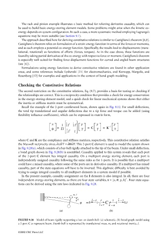
in Fig. 9.28(a), which consists of a bar-bell rigidly attached to the tip of the beam. Under small deflection,
a bond graph shown in Fig. 9.28(b) is assembled. Causality applied to this system reveals that each port
of the 2-port C element has integral causality. On a multiport energy storing element, each port is
independently assigned causality following the same rules as for 1-ports. It is possible that a multiport
could have a mixed causality, where some of the ports are in derivative causality. If a multiport has mixed
causality, part of the state equations will have to be inverted. This algebraic difficulty is best avoided by
trying to assign integral causality to all multiport elements in a system model if possible.
In the present example, causality assignment on the I elements is also integral. In all, there are four
independent energy-storing elements, so there are four state variables, x = [x, θ, p, h] . Four state equa-
tions can be derived using the rate laws indicated in Fig. 9.28.
m, J
x
p = F F T h = T
θ m:I 1 C 1 I:J
x = V θ ω
=
(a) (b)
FIGURE 9.28 Model of beam rigidly supporting a bar- or dumb-bell: (a) schematic, (b) bond graph model using
a 2-port C to represent beam. Dumb-bell is represented by translational mass, m, and rotational inertia, J.
©2002 CRC Press LLC