
Page 151 - The Mechatronics Handbook
P. 151
V mass
1 Ma s s e 1 I:m S e 1 I:m
V mass S 7 8
V z
6
C:k -1 C:k -1
V re la t ive
5
0 1 0 1 0 1
V re la t ive 3
4
R:b R:b
2
1 1
V ba s e Ba s e S 1 S
V = 0 f 1 f
V ba s e
(fix e d ba s e )
(a ) (b ) (c)
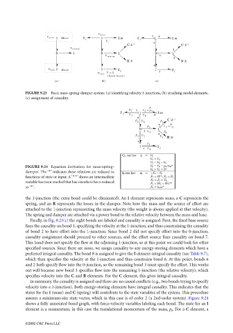
FIGURE 9.23 Basic mass-spring-damper system: (a) identifying velocity 1-junctions, (b) attaching model elements,
(c) assignment of causality.
FIGURE 9.24 Equation derivation for mass-spring-
damper. The ‘*’ indicates these relations are reduced to
functions of state or input. A ‘**’ shows an intermediate
variable has been reached that has elsewhere been reduced
to ‘*’.
the 1-junction (the extra bond could be eliminated). An I element represents mass, a C represents the
spring, and an R represents the losses in the damper. Note how the mass and the source of effort are
attached to the 1-junction representing the mass velocity (the weight is always applied at that velocity).
The spring and damper are attached via a power bond to the relative velocity between the mass and base.
Finally, in Fig. 9.23(c) the eight bonds are labeled and causality is assigned. First, the fixed base source
fixes the causality on bond 1, specifying the velocity at the 1-junction, and thus constraining the causality
of bond 2 to have effort into the 1-junction. Since bond 2 did not specify effort into the 0-junction,
causality assignment should proceed to other sources, and the effort source fixes causality on bond 7.
This bond does not specify the flow at the adjoining 1-junction, so at this point we could look for other
specified sources. Since there are none, we assign causality to any energy-storing elements which have a
preferred integral causality. The bond 8 is assigned to give the I element integral causality (see Table 9.7),
which then specifies the velocity at the 1-junction and thus constrains bond 6. At this point, bonds 6
and 2 both specify flow into the 0-junction, so the remaining bond 3 must specify the effort. This works
out well because now bond 3 specifies flow into the remaining 1-junction (the relative velocity), which
specifies velocity into the C and R elements. For the C element, this gives integral causality.
In summary, the causality is assigned and there are no causal conflicts (e.g., two bonds trying to specify
velocity into a 1-junction). Both energy-storing elements have integral causality. This indicates that the
states for the I (mass) and C (spring) will contribute to the state variables of the system. This procedure
assures a minimum-size state vector, which in this case is of order 2 (a 2nd-order system). Figure 9.24
shows a fully annotated bond graph, with force-velocity variables labeling each bond. The state for an I
element is a momentum, in this case the translational momentum of the mass, p 8 . For a C element, a
©2002 CRC Press LLC