Page 146 - The Mechatronics Handbook
P. 146

When modeling simple translational systems or fixed-axis rotational systems, the basic set of laws
                                 summarized below are sufficient to build the necessary mathematical models.

                                                             Basic Dynamic and Kinematic Laws
                                                         System        Dynamics    Kinematics
                                                                                  N
                                                                       N
                                                         Translational     ∑ i  F i =  0  ∑ i  V i =  0
                                                                       N
                                                         Rotational   ∑ i  T i =  0    ∑ i  w i =  0
                                                                                  N
                                                         Junction type    1-junction    0-junction
                                   There is a large class of mechanical systems that can be represented using these basic equations, and
                                 in this form it is possible to see how: (a) bond graph junction elements can be used to structure these
                                 models and (b) how these equations support circuit analog equations, since they are very similar to the
                                 Kirchhoff circuit laws for voltage and current. We present here the bond graph approach, which graph-
                                 ically communicates these physical laws through the 0- and 1-junction elements.


                                 Identifying and Representing Motion in a Bond Graph
                                 It is helpful when studying a mechanical system to focus on identifying points in the system that have
                                 distinct velocities (V or ω). One simply can associate a 1-junction with these points. Once this is done,
                                 it becomes easier to identify connection points for other mechanical components (masses, springs, damp-
                                 ers, etc.) as well as points for attaching actuators or sensors. Further, it is critical to identify and to define
                                 additional velocities associated with relative motion. These may not have clear, physically identifiable points
                                 in a system, but it is necessary to localize these in order to attach components that rely on relative motion
                                 to describe their operation (e.g., suspensions).
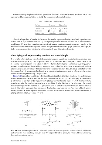
                                   Figure 9.20 shows how identifying velocities of interest can help identify 1-junctions at which mechan-
                                 ical components can be attached. For the basic mass element in part (a), the underlying premise is that
                                 a component of a system under study is idealized as a pure translational mass for which momentum and
                                 velocity are related through a constitutive relation. What this implies is that the velocity of the mass is
                                 the same throughout this element, so a 1-junction is used to identify this distinct motion. A bond attached
                                 to this 1-junction represents how any power flowing into this junction can flow into a kinetic energy
                                 storing element, I, which represents the mass, m. Note that the force on the bond is equal to the rate of
                                                    p ˙
                                 change of momentum,  , where p = mV.


                                                                                             J
                                                    V               V 1  K       V 2          1  J 2  ω
                                                                                            ω
                                                                                             1      2
                                               m                m 1          m 2
                                                                I: m         I: m       I: J         I: J
                                                                   1            2          1            2
                                                                                                 µ
                                            1      I: m
                                               V
                                          Simple translating mass defines distinct  1  V  0  V  1  1  0  ω  1
                                          velocity.  Attach the I-element to the  V  1  2  V  ω  ω 1  2  ω
                                          corresponding 1-junction.  1  V     2          1      ω     2
                                                                        3                        3
                                                                       1     C: 1/K            1     R
                                                                relative  x             relative  ω
                                                                velocity                velocity
                                               (a)                     (b)                    (c)

                                 FIGURE 9.20  Identifying velocities in a mechanical system can help identify correct interconnection of components
                                 and devices: (a) basic translating mass, (b) basic two-degree of freedom system, (c) rotational frictional coupling
                                 between two rotational inertias.


                                 ©2002 CRC Press LLC
   141   142   143   144   145   146   147   148   149   150   151