
Page 141 - The Mechatronics Handbook
P. 141
Cylindrical shell
Pointmass atradius r c
about axis c c
-
(inner radius r)
J = mr 2 J mr 2
c =
If outer radius is R,and
not a thin shell,
( )
Rod or bar about centroid J = 1 2 m R 2 + r 2
mL 2
J =
12
L c Cylinder about axis c-c
(radius r)
J 1 mr 2
Short bar about pivot = 2
c
m
2
J = + (d 2 4 )
l
L 12
Slender bar case, d=0
d
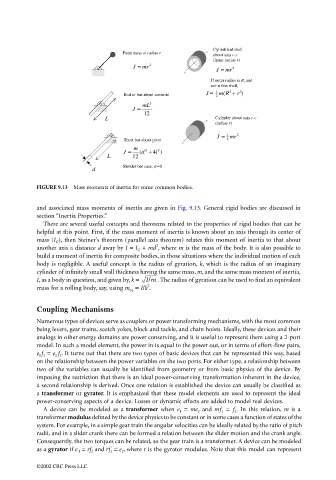
FIGURE 9.13 Mass moments of inertia for some common bodies.
and associated mass moments of inertia are given in Fig. 9.13. General rigid bodies are discussed in
section “Inertia Properties.”
There are several useful concepts and theorems related to the properties of rigid bodies that can be
helpful at this point. First, if the mass moment of inertia is known about an axis through its center of
mass (I G ), then Steiner’s theorem (parallel axis theorem) relates this moment of inertia to that about
2
another axis a distance d away by I = I G + md , where m is the mass of the body. It is also possible to
build a moment of inertia for composite bodies, in those situations where the individual motion of each
body is negligible. A useful concept is the radius of gyration, k, which is the radius of an imaginary
cylinder of infinitely small wall thickness having the same mass, m, and the same mass moment of inertia,
I, as a body in question, and given by, k = I/m . The radius of gyration can be used to find an equivalent
2
mass for a rolling body, say, using m eq = I/k .
Coupling Mechanisms
Numerous types of devices serve as couplers or power transforming mechanisms, with the most common
being levers, gear trains, scotch yokes, block and tackle, and chain hoists. Ideally, these devices and their
analogs in other energy domains are power conserving, and it is useful to represent them using a 2-port
model. In such a model element, the power in is equal to the power out, or in terms of effort-flow pairs,
e 1 f 1 = e 2 f 2 . It turns out that there are two types of basic devices that can be represented this way, based
on the relationship between the power variables on the two ports. For either type, a relationship between
two of the variables can usually be identified from geometry or from basic physics of the device. By
imposing the restriction that there is an ideal power-conserving transformation inherent in the device,
a second relationship is derived. Once one relation is established the device can usually be classified as
a transformer or gyrator. It is emphasized that these model elements are used to represent the ideal
power-conserving aspects of a device. Losses or dynamic effects are added to model real devices.
A device can be modeled as a transformer when e 1 = me 2 and mf 1 = f 2 . In this relation, m is a
transformer modulus defined by the device physics to be constant or in some cases a function of states of the
system. For example, in a simple gear train the angular velocities can be ideally related by the ratio of pitch
radii, and in a slider crank there can be formed a relation between the slider motion and the crank angle.
Consequently, the two torques can be related, so the gear train is a transformer. A device can be modeled
as a gyrator if e 1 = rf 2 and rf 1 = e 2 , where r is the gyrator modulus. Note that this model can represent
©2002 CRC Press LLC