
Page 144 - The Mechatronics Handbook
P. 144
0066-frame-C09 Page 18 Friday, January 18, 2002 10:59 AM
TABLE 9.6 Basic Mechanical Impedance Elements
System Resistive, Z R Capacitive, Z C Inertive, Z I
Translation b k/s m · s
Rotation B K/s J · s
Z Z
Z 1 1
1
e e
Z Z 1 Z Z Z Z Z 0 Z
2 f 2 1 2 3 f 2
Z
3
Z Z
3 3
(a) (b)
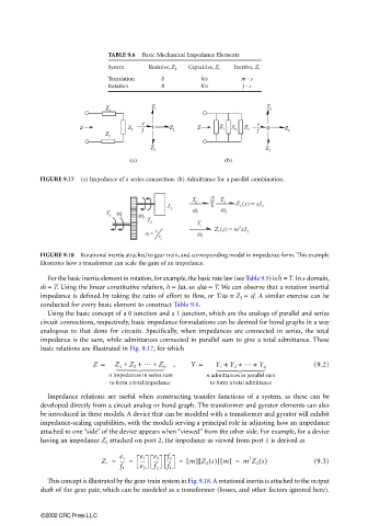
FIGURE 9.17 (a) Impedance of a series connection. (b) Admittance for a parallel combination.
m
T 1 .. T 2 () =
J 2 T ω Zs sJ 2
2
T ω ω ω 1 2
1 1
2 T
2 T
() =
1 Zs m sJ
2
m = 1 r ω 1 2
2 r 1
FIGURE 9.18 Rotational inertia attached to gear train, and corresponding model in impedance form. This example
illustrates how a transformer can scale the gain of an impedance.
˙
For the basic inertia element in rotation, for example, the basic rate law (see Table 9.5) is = T. In s-domain,
h
sh = T. Using the linear constitutive relation, h = Jω, so sJω = T. We can observe that a rotation inertial
impedance is defined by taking the ratio of effort to flow, or T/ω ≡ Z I = sJ. A similar exercise can be
conducted for every basic element to construct Table 9.6.
Using the basic concept of a 0 junction and a 1 junction, which are the analogs of parallel and series
circuit connections, respectively, basic impedance formulations can be derived for bond graphs in a way
analogous to that done for circuits. Specifically, when impedances are connected in series, the total
impedance is the sum, while admittances connected in parallel sum to give a total admittance. These
basic relations are illustrated in Fig. 9.17, for which
Z = Z 1 + Z 2 + … + Z n , Y = Y 1 + Y 2 + … + Y n (9.2)
n impedances in series sum n admittances in parallel sum
to form a total impedance to form a total admittance
Impedance relations are useful when constructing transfer functions of a system, as these can be
developed directly from a circuit analog or bond graph. The transformer and gyrator elements can also
be introduced in these models. A device that can be modeled with a transformer and gyrator will exhibit
impedance-scaling capabilities, with the moduli serving a principal role in adjusting how an impedance
attached to one “side” of the device appears when “viewed” from the other side. For example, for a device
having an impedance Z 2 attached on port 2, the impedance as viewed from port 1 is derived as
2
m Z 2 s()[
Z 1 = ---- = e 1 e 2 --- = [] ] m[] = m Z 2 s() (9.3)
f 2
e 1
----
----
f 1 e 2 f 2 f 1
This concept is illustrated by the gear-train system in Fig. 9.18. A rotational inertia is attached to the output
shaft of the gear pair, which can be modeled as a transformer (losses, and other factors ignored here).
©2002 CRC Press LLC