
Page 148 - The Mechatronics Handbook
P. 148
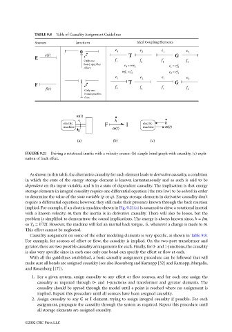
TABLE 9.8  Table of Causality Assignment Guidelines
                                      Sources          Junctions                  Ideal Coupling Elements
                                                                        e          e         e         e
                                                         0               1          2        1          2
                                          e(t)                                T                   G
                                      E
                                                           Only one     f 1        f 2       f 1       f 2
                                                           bond specifies
                                                                            e 1 = me 2          e 1 = rf 2
                                                           effort.
                                                                           mf 1 = f 2           e 2 = rf 1
                                                                        e 1        e 2       e 1       e
                                                         1                    T                   G     2
                                      F                                 f
                                          f(t)                           1         f 2       f 1       f  2
                                                           Only one
                                                           bond specifies
                                                           flow.

                                                        ω(t)
                                                                        h
                                                  electric          F        I       electric  h
                                                  machine              ω(t)          machine  ω(t)


                                                        (a)            (b)              (c)

                                 FIGURE 9.21  Driving a rotational inertia with a velocity source: (b) simple bond graph with causality, (c) expla-
                                 nation of back effect.


                                   As shown in this table, the alternative causality for each element leads to derivative causality, a condition
                                 in which the state of the energy storage element is known instantaneously and as such is said to be
                                 dependent on the input variable, and is in a state of dependent causality. The implication is that energy
                                 storage elements in integral causality require one differential equation (the rate law) to be solved in order
                                 to determine the value of the state variable (p or q). Energy storage elements in derivative causality don’t
                                 require a differential equation; however, they still make their presence known through the back reaction
                                 implied. For example, if an electric machine shown in Fig. 9.21(a) is assumed to drive a rotational inertial
                                 with a known velocity, ω, then the inertia is in derivative causality. There will also be losses, but the
                                 problem is simplified to demonstrate the causal implications. The energy is always known since, h = Jω,
                                                                                      ˙
                                        2
                                                                                      h
                                 so T h  = h /2J. However, the machine will feel an inertial back torque,  , whenever a change is made to ω.
                                 This effect cannot be neglected.
                                   Causality assignment on some of the other modeling elements is very specific, as shown in Table 9.8.
                                 For example, for sources of effort or flow, the causality is implied. On the two-port transformer and
                                 gyrator, there are two possible causality arrangements for each. Finally, for 0- and 1-junctions, the causality
                                 is also very specific since in each case only one bond can specify the effort or flow at each.
                                   With all the guidelines established, a basic causality assignment procedure can be followed that will
                                 make sure all bonds are assigned causality (see also Rosenberg and Karnopp [32] and Karnopp, Margolis,
                                 and Rosenberg [17]).

                                    1. For a given system, assign causality to any effort or flow sources, and for each one assign the
                                       causality as required through 0- and 1-junctions and transformer and gyrator elements. The
                                       causality should be spread through the model until a point is reached where no assignment is
                                       implied. Repeat this procedure until all sources have been assigned causality.
                                    2. Assign causality to any C or I element, trying to assign integral causality if possible. For each
                                       assignment, propagate the causality through the system as required. Repeat this procedure until
                                       all storage elements are assigned causality.

                                 ©2002 CRC Press LLC