
Page 136 - The Mechatronics Handbook
P. 136
e
1 n Resistive e
e 1 e n R R e = Φ ( f )
Causality f R
f 1 f n
f
e 2
2 R T
f 2
e
f s e
Conductive -1
Thermal Causality R
e 3 f 3 R
port f f = Φ (e)
3 R
f
(a) (b)
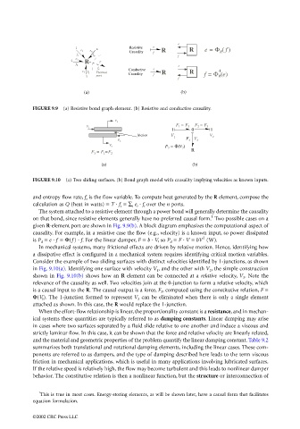
FIGURE 9.9 (a) Resistive bond graph element. (b) Resistive and conductive causality.
V 1
F 1 = F 3 F 2 = F 3
F 1
1 0 1
friction V V
1 2
F V
F 2 3 3
F 3 = Φ(V 3 )
V 2
R
F 3 = F 1 =F 2
(a) (b)
FIGURE 9.10 (a) Two sliding surfaces. (b) Bond graph model with causality implying velocities as known inputs.
and entropy flow rate, f s is the flow variable. To compute heat generated by the R element, compose the
calculation as Q (heat in watts) = T · f s = ∑ i e i · f i over the n ports.
The system attached to a resistive element through a power bond will generally determine the causality
1
on that bond, since resistive elements generally have no preferred causal form. Two possible cases on a
given R-element port are shown in Fig. 9.9(b). A block diagram emphasizes the computational aspect of
causality. For example, in a resistive case the flow (e.g., velocity) is a known input, so power dissipated
2
is P d = e · f = Φ(f ) · f. For the linear damper, F = b · V, so P d = F · V = bV (W).
In mechanical systems, many frictional effects are driven by relative motion. Hence, identifying how
a dissipative effect is configured in a mechanical system requires identifying critical motion variables.
Consider the example of two sliding surfaces with distinct velocities identified by 1-junctions, as shown
in Fig. 9.10(a). Identifying one surface with velocity V 1 , and the other with V 2 , the simple construction
shown in Fig. 9.10(b) shows how an R element can be connected at a relative velocity, V 3 . Note the
relevance of the causality as well. Two velocities join at the 0-junction to form a relative velocity, which
is a causal input to the R. The causal output is a force, F 3 , computed using the constitutive relation, F =
Φ(V 3 ). The 1-junction formed to represent V 3 can be eliminated when there is only a single element
attached as shown. In this case, the R would replace the 1-junction.
When the effort-flow relationship is linear, the proportionality constant is a resistance, and in mechan-
ical systems these quantities are typically referred to as damping constants. Linear damping may arise
in cases where two surfaces separated by a fluid slide relative to one another and induce a viscous and
strictly laminar flow. In this case, it can be shown that the force and relative velocity are linearly related,
and the material and geometric properties of the problem quantify the linear damping constant. Table 9.2
summarizes both translational and rotational damping elements, including the linear cases. These com-
ponents are referred to as dampers, and the type of damping described here leads to the term viscous
friction in mechanical applications, which is useful in many applications involving lubricated surfaces.
If the relative speed is relatively high, the flow may become turbulent and this leads to nonlinear damper
behavior. The constitutive relation is then a nonlinear function, but the structure or interconnection of
1
This is true in most cases. Energy-storing elements, as will be shown later, have a causal form that facilitates
equation formulation.
©2002 CRC Press LLC