
Page 343 - The Mechatronics Handbook
P. 343
AC or DC power supply. They are normally used in fractional horsepower application. The DC universal
motor has the highest horsepower-per-pound ratio, but has a relatively short operating life.
The stepper motor is a discrete (incremental) positioning device that moves one step at a time for each
pulse command input. Since they accept direct digital commands and produce a mechanical motion, the
stepper motors are used widely in industrial control applications. They are mostly used in fractional
horsepower applications. With the rapid progress in low cost and high frequency solid-state drives, they
are finding increased applications.
Figure 16.9 shows a simplified unipolar stepper motor. The
winding-1 is between the top and bottom stator pole, and the
winding-2 is between the left and right motor poles. The rotor is 1
N
a permanent magnet with six poles resulting in a single step angle
of 30∞. With appropriate excitation of winding-1, the top stator N S N
2 2
pole becomes a north pole and the bottom stator pole becomes S S
a south pole. This attracts the rotor into the position as shown. N
Now if the winding-1 is de-energized and winding-2 is energized, S 1
the rotor will turn 30∞. With appropriate choice of current flow
through winding-2, the rotor can be rotated either clockwise or FIGURE 16.9 Unipolar stepper motor.
counterclockwise. By exciting the two windings in sequence, the
motor can be made to rotate at a desired speed continuously.
Electromagnetic Actuators
The solenoid is the most common electromagnetic actuator. A DC solenoid actuator consists of a soft
iron core enclosed within a current carrying coil. When the coil is energized, a magnetic field is established
that provides the force to push or pull the iron core. AC solenoid devices are also encountered, such as
AC excitation relay.
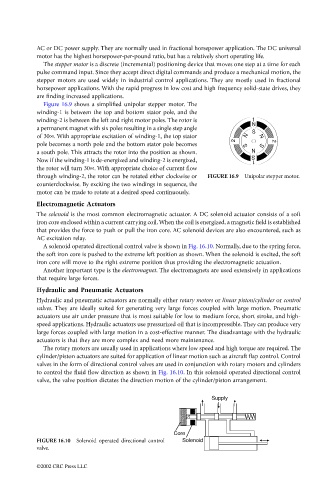
A solenoid operated directional control valve is shown in Fig. 16.10. Normally, due to the spring force,
the soft iron core is pushed to the extreme left position as shown. When the solenoid is excited, the soft
iron core will move to the right extreme position thus providing the electromagnetic actuation.
Another important type is the electromagnet. The electromagnets are used extensively in applications
that require large forces.
Hydraulic and Pneumatic Actuators
Hydraulic and pneumatic actuators are normally either rotary motors or linear piston/cylinder or control
valves. They are ideally suited for generating very large forces coupled with large motion. Pneumatic
actuators use air under pressure that is most suitable for low to medium force, short stroke, and high-
speed applications. Hydraulic actuators use pressurized oil that is incompressible. They can produce very
large forces coupled with large motion in a cost-effective manner. The disadvantage with the hydraulic
actuators is that they are more complex and need more maintenance.
The rotary motors are usually used in applications where low speed and high torque are required. The
cylinder/piston actuators are suited for application of linear motion such as aircraft flap control. Control
valves in the form of directional control valves are used in conjunction with rotary motors and cylinders
to control the fluid flow direction as shown in Fig. 16.10. In this solenoid operated directional control
valve, the valve position dictates the direction motion of the cylinder/piston arrangement.
Supply
Core
FIGURE 16.10 Solenoid operated directional control Solenoid
valve.
©2002 CRC Press LLC