
Page 340 - The Mechatronics Handbook
P. 340
the sensor and its output recorded to establish a correct output scale. This process proves the ability to
measure reliably and enhances the confidence.
If the sensor is used to measure a time-varying input, dynamic calibration becomes necessary. Use of
sinusoidal inputs is the most simple and reliable way of dynamic calibration. However, if generating
sinusoidal input becomes impractical (for example, temperature signals) then a step input can substitute
for the sinusoidal signal. The transient behavior of step response should yield sufficient information
about the dynamic response of the sensor.
16.2 Actuators
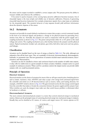
Actuators are basically the muscle behind a mechatronics system that accepts a control command (mostly
in the form of an electrical signal) and produces a change in the physical system by generating force,
motion, heat, flow, etc. Normally, the actuators are used in conjunction with the power supply and a
coupling mechanism as shown in Fig. 16.7. The power unit provides either AC or DC power at the rated
voltage and current. The coupling mechanism acts as the interface between the actuator and the physical
system. Typical mechanisms include rack and pinion, gear drive, belt drive, lead screw and nut, piston,
and linkages.
Classification
Actuators can be classified based on the type of energy as listed in Table 16.2. The table, although not
exhaustive, lists all the basic types. They are essentially of electrical, electromechanical, electromagnetic,
hydraulic, or pneumatic type. The new generations of actuators include smart material actuators, micro-
actuators, and Nanoactuators.
Actuators can also be classified as binary and continuous based on the number of stable-state outputs.
A relay with two stable states is a good example of a binary actuator. Similarly, a stepper motor is a good
example of continuous actuator. When used for a position control, the stepper motor can provide stable
outputs with very small incremental motion.
Principle of Operation
Electrical Actuators
Electrical switches are the choice of actuators for most of the on-off type control action. Switching devices
such as diodes, transistors, triacs, MOSFET, and relays accept a low energy level command signal from
the controller and switch on or off electrical devices such as motors, valves, and heating elements. For
example, a MOSFET switch is shown in Fig. 16.8. The gate terminal receives the low energy control signal
from the controller that makes or breaks the connection between the power supply and the actuator load.
When switches are used, the designer must make sure that switch bounce problem is eliminated either
by hardware or software.
Electromechanical Actuators
The most common electromechanical actuator is a motor that converts electrical energy to mechanical
motion. Motors are the principal means of converting electrical energy into mechanical energy in industry.
Broadly they can be classified as DC motors, AC motors, and stepper motors. DC motors operate on DC
ACTUATING UNIT
POWER
SUPPLY
FROM COUPLING
TO
CONTROLLER ACTUATOR MECHANISM CONTROLLED
SYSTEM
FIGURE 16.7 A typical actuating unit.
©2002 CRC Press LLC