
Page 337 - The Mechatronics Handbook
P. 337
CONTROL UNIT
R R
T T
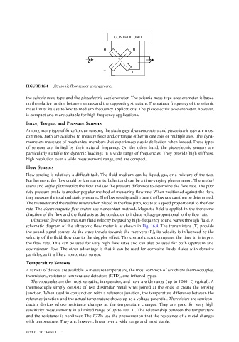
FIGURE 16.4 Ultrasonic flow sensor arrangement.
the seismic mass type and the piezoelectric accelerometer. The seismic mass type accelerometer is based
on the relative motion between a mass and the supporting structure. The natural frequency of the seismic
mass limits its use to low to medium frequency applications. The piezoelectric accelerometer, however,
is compact and more suitable for high frequency applications.
Force, Torque, and Pressure Sensors
Among many type of force/torque sensors, the strain gage dyanamometers and piezoelectric type are most
common. Both are available to measure force and/or torque either in one axis or multiple axes. The dyna-
mometers make use of mechanical members that experiences elastic deflection when loaded. These types
of sensors are limited by their natural frequency. On the other hand, the piezoelectric sensors are
particularly suitable for dynamic loadings in a wide range of frequencies. They provide high stiffness,
high resolution over a wide measurement range, and are compact.
Flow Sensors
Flow sensing is relatively a difficult task. The fluid medium can be liquid, gas, or a mixture of the two.
Furthermore, the flow could be laminar or turbulent and can be a time-varying phenomenon. The venturi
meter and orifice plate restrict the flow and use the pressure difference to determine the flow rate. The pitot
tube pressure probe is another popular method of measuring flow rate. When positioned against the flow,
they measure the total and static pressures. The flow velocity and in turn the flow rate can then be determined.
The rotameter and the turbine meters when placed in the flow path, rotate at a speed proportional to the flow
rate. The electromagnetic flow meters use noncontact method. Magnetic field is applied in the transverse
direction of the flow and the fluid acts as the conductor to induce voltage proportional to the flow rate.
Ultrasonic flow meters measure fluid velocity by passing high-frequency sound waves through fluid. A
schematic diagram of the ultrasonic flow meter is as shown in Fig. 16.4. The transmitters (T) provide
the sound signal source. As the wave travels towards the receivers (R), its velocity is influenced by the
velocity of the fluid flow due to the doppler effect. The control circuit compares the time to interpret
the flow rate. This can be used for very high flow rates and can also be used for both upstream and
downstream flow. The other advantage is that it can be used for corrosive fluids, fluids with abrasive
particles, as it is like a noncontact sensor.
Temperature Sensors
A variety of devices are available to measure temperature, the most common of which are thermocouples,
thermisters, resistance temperature detectors (RTD), and infrared types.
Thermocouples are the most versatile, inexpensive, and have a wide range (up to 1200∞C typical). A
thermocouple simply consists of two dissimilar metal wires joined at the ends to create the sensing
junction. When used in conjunction with a reference junction, the temperature difference between the
reference junction and the actual temperature shows up as a voltage potential. Thermisters are semicon-
ductor devices whose resistance changes as the temperature changes. They are good for very high
sensitivity measurements in a limited range of up to 100∞C. The relationship between the temperature
and the resistance is nonlinear. The RTDs use the phenomenon that the resistance of a metal changes
with temperature. They are, however, linear over a wide range and most stable.
©2002 CRC Press LLC