
Page 336 - The Mechatronics Handbook
P. 336
analog-to-digital conversion before feeding to the digital controller. Digital sensors on the other hand
produce digital outputs that can be directly interfaced with the digital controller. Often, the digital outputs
are produced by adding an analog-to-digital converter to the sensing unit. If many sensors are required,
it is more economical to choose simple analog sensors and interface them to the digital controller
equipped with a multi-channel analog-to-digital converter.
Principle of Operation
Linear and Rotational Sensors
Linear and rotational position sensors are two of the most fundamental of all measurements used in a
typical mechatronics system. The most common type position sensors are listed in Table 16.1. In general,
the position sensors produce an electrical output that is proportional to the displacement they experience.
There are contact type sensors such as strain gage, LVDT, RVDT, tachometer, etc. The noncontact type
includes encoders, hall effect, capacitance, inductance, and interferometer type. They can also be classified
based on the range of measurement. Usually the high-resolution type of sensors such as hall effect, fiber
optic inductance, capacitance, and strain gage are suitable for only very small range (typically from 0.1 mm
to 5 mm). The differential transformers on the other hand, have a much larger range with good resolution.
Interferometer type sensors provide both very high resolution (in terms of microns) and large range of
measurements (typically up to a meter). However, interferometer type sensors are bulky, expensive, and
requires large set up time.
Among many linear displacement sensors, strain gage provides high
resolution at low noise level and is least expensive. A typical resistance
strain gage consists of resistive foil arranged as shown in the Fig. 16.2.
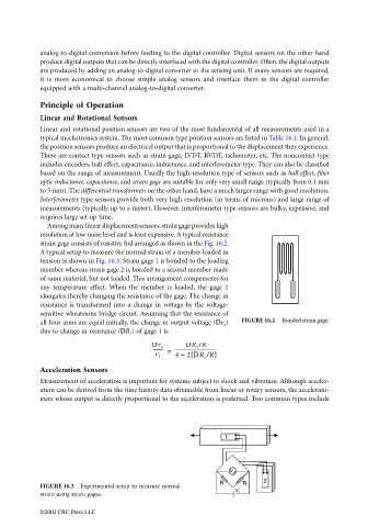
A typical setup to measure the normal strain of a member loaded in
tension is shown in Fig. 16.3. Strain gage 1 is bonded to the loading
member whereas strain gage 2 is bonded to a second member made
of same material, but not loaded. This arrangement compensates for
any temperature effect. When the member is loaded, the gage 1
elongates thereby changing the resistance of the gage. The change in
resistance is transformed into a change in voltage by the voltage-
sensitive wheatstone bridge circuit. Assuming that the resistance of
all four arms are equal initially, the change in output voltage (Dv o ) FIGURE 16.2 Bonded strain gage.
due to change in resistance (DR 1 ) of gage 1 is
DR 1 /R
Dv o
-------- = ----------------------------------
(
v i 4 + 2 DR 1 /R)
Acceleration Sensors
Measurement of acceleration is important for systems subject to shock and vibration. Although acceler-
ation can be derived from the time history data obtainable from linear or rotary sensors, the accelerom-
eters whose output is directly proportional to the acceleration is preferred. Two common types include
1
v o
2
R R
FIGURE 16.3 Experimental setup to measure normal
v
strain using strain gages. i
©2002 CRC Press LLC