Page 398 - The Mechatronics Handbook
P. 398

In Eq. (19.12), it is assumed that the damping force on the seismic mass is proportional to velocity
                                 only. If a harmonic vibratory motion is impressed on the instrument such that

                                                                 x 1 t() =  X 0 sin ( ω  1 t)             (19.14)

                                 where ω 1  is the frequency of vibration (rad/s), writing

                                                                   2
                                                                  d x 1
                                                                     2 =
                                                                -m ----------  mX 0 sin ω  1 t
                                                                   dt
                                 modifies Eq. (19.13) as

                                                          2
                                                         d z  dz
                                                       m ------- 2 +  c -----  +  kz   mgcos=  θ () +  ma 1 sin ω  1 t  (19.15)
                                                         dt    dt
                                                2
                                 where a 1  = mX 0 w 1  .
                                   Equation (19.15) will have transient and steady-state solutions. The steady-state solution of the dif-
                                 ferential equation (19.15) may be determined as

                                                               mgcos  θ ()  ma 1 sin ω  1 t
                                                           z =  ------------------------  +  -----------------------------------------  (19.16)
                                                                                2
                                                                  k      ( k mω 1 +–  jcω 1 )
                                 Rearranging Eq. (19.16) results in

                                                                                   –
                                                             mgcos  θ ()  a 1 sin ( ω  1 t  φ)
                                                         z =  ------------------------  +  ----------------------------------------------------  (19.17)
                                                                ω n       2    2 2      2
                                                                         ω n 1 r–(  ) +  ( 2zr)
                                 where ω n  (= k/m ) is the natural frequency of the seismic mass,  V   (=c/2 km ) is the damping ratio.
                                 The damping ratio can be written in terms of the critical damping ratio as   = c/c c , where c c  =V  2 km ,
                                       -1          2
                                 φ (=tan  [cω 1 /(k - mw 1 )]) is the phase angle, and r (=ω 1 /ω n ) is the frequency ratio.
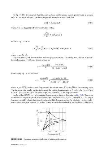
                                   A plot of Eq. (19.17), (x 1  - x 2 ) 0 /x 0  against frequency ratio ω 1 /ω n , is illustrated in Fig. 19.21. This figure
                                 shows that the output amplitude is equal to the input amplitude when c/c c  = 0.7 and ω 1 /ω n  > 2. The output
                                 becomes essentially a linear function of the input at high frequency ratios. For satisfactory system perfor-
                                 mance, the instrument constant c/c c  and ω n  should be carefully calculated or obtained from calibrations.


                                 FIGURE 19.21  Frequency versus amplitude ratio of seismic accelerometers.

                                 ©2002 CRC Press LLC
   393   394   395   396   397   398   399   400   401   402   403